To my Angel.
Preface
In 1989, I went to college to study business informatics, or applied computer science. One of the classes I took was Software Engineering. It taught us the process of how to develop software.
In my first job out of college, I ran into problems applying this process. Subject-matter experts didn’t agree on the requirements. And when they did agree, they changed their minds, even after implementation was complete. During implementation, we’d find issues with the design. Budget and schedule overruns of 200% were common.
In my youthful ignorance, I blamed fickle customers. My second job was working for a product company, where I didn’t interact directly with customers anymore. That didn’t solve my problems, though. We had fixed scope and deadlines, resulting in poor quality and lots of time spent fixing bugs.
In my third job I read [Beck2000] and started to see a way out of the misery. I introduced eXtreme Programming into the organization and achieved some initial successes. At the first bump in the road, however, the CEO forbid us to do any more pair programming.
And so it continued with every job I had after that. I’ve never had the feeling that we as an industry have figured out how to do software development well. It has never felt like engineering to me.
This book is my attempt to survey the field and see how far away that ideal is.
The material that follows is in written form, because I firmly believe that writing is thinking. It’s a book rather than a blog post or series of posts because there is a lot of ground to cover. Writing this book is the most ambitious thing I’ve ever done. I may not even finish it, but I’m sure I’ll learn a lot on the way. And maybe it’ll help you too.
Ray Sinnema
November 2023
Introduction
This part of the book builds the foundations for the rest of the book. We start by introducing engineering and software. We then put them together to get a sense of what software engineering should look like. We conclude with a word on the organization of the book and the origin of its title.
Engineering
If the goal is for software development to be an engineering discipline, then we should understand what engineering means.
Engineering is the creation of cost-effective solutions to practical problems by applying scientific knowledge to build things in the service of mankind.
— [Shaw1990]
One of the essential parts in this definition is that engineering is about building things. Where science is about discovering how things are, engineering is about discovering a form for an artifact that ensures it serves its purpose [Brockman2009].
Another essential part is applying science. If the required science isn’t available yet, we can settle for codified knowledge instead. If there are no generally accepted principles and procedures at all, however, then it’s craft rather than engineering [Shaw1990].
Science
Science is a system of knowledge covering general truths or the operation of general laws, especially as obtained and tested through the scientific method.
The scientific method are principles and procedures for the systematic pursuit of knowledge involving the recognition and formulation of a problem, the collection of data through observation and experiment, and the formulation and testing of hypotheses.
The scientific method involves making observations, formulating hypotheses based on those observations, running experiments to falsify the hypotheses, and generalizing hypotheses into a cohesive theory. These activities form a loop:
flowchart LR
  Hypothesis --Design an\nexperiment to\ntest the hypothesis--> Experiment
  Experiment --Perform the\nexperiment--> Observation
  Observation --Create or modify\nthe theory--> Theory
  Theory --Use the theory\nto form a\nhypothesis--> Hypothesis
Scientific knowledge grows over time. Little discoveries here and there build on each other to reach truly impressive gains in understanding. Most of this progress is gradual. Every once in a while, however, a breakthrough leads to rapid progress. Some of these breakthroughs are the result of a different way of looking at things [Kuhn1970].
Applying science
Application of the scientific method leads to scientific theories that engineering then applies to solve practical problems. For instance, electrical engineering applies the theory of electromagnetism [Jackson1999].
The methodical and iterative transition between scientific theory and its practical application successively develops and refines both the theory itself and its application. This forms the essence of good engineering practice [Voland2004].
Engineers must acquire broad and deep technical knowledge, which begins with an understanding of scientific principles. State-of-the-art designs require a deep understanding of one or more specialized engineering domains. A broad view of how such an area of expertise relates to other domains provides opportunities to apply knowledge in novel ways. Engineers must also be familiar with historical design failures to avoid repeating the mistakes of the past.
Engineers apply scientific theories by constructing models of their designs [Brockman2009]. A model is an approximation of a real system that responds in a similar way.
Since everything connects to everything, networks are important models. A graph is a visualization of a network, where the nodes are things and the edges are relationships between the things. Edges are either directed (with arrows) or undirected (without).
Here’s an example of an undirected graph:
graph LR
  a((a)) --- b((b))
  b --- c((c))
  c --- d((d))
  c --- e((e))
  c --- f((f))
  e --- f
  f --- g((g))
  b --- h((h))
  h --- i((i))
  c --- i
  i --- j((j))
A concept map is a graph where the nodes represent concepts and the edges the relationships between them. Concepts maps are useful for organizing and structuring knowledge.
A system is part of a network inside a boundary [Brockman2009]. Everything outside the boundary is the environment. Systems can consist of subsystems, which are also systems. Systems are often more than the sum of their parts.
Systems are important for engineering because:
- They’re more robust: fewer dependencies means fewer things that can go wrong.
- They’re easier to reason about: instead of having to understand everything inside a subsystem, we can temporarily forget about irrelevant details.
- Engineers can re-use existing designs when incorporating subsystems into the systems they’re designing.
Many systems are hierarchical in nature. A graph of such a system is a tree, which is usually drawn upside-down, with the root at the top. A node directly above another node is a parent node and the node below it its child. A node without children is a leaf. A node that’s neither the root nor a leaf is an intermediate node.
A parts hierarchy or structural hierarchy is a tree where all relationships are has-part.
A class hierarchy or taxonomy is a tree where all relationships are is-a.
Design process
Engineers focus on problems for which there are many practical solutions. They seek the best solution from among these alternatives. To help with that, they follow a procedure known as the engineering design process [Voland2004].
The artifacts to design have form and purpose, and the form must be appropriate for the purpose [Brockman2009]. A producer produces an artifact in the engineering environment, while an operator uses the artifact in the operating environment.
Operators have performance goals, or specifications. Producers have cost goals, or requirements. An engineer expresses goals quantitatively as constraints or objectives. A constraint is a hard limit, for instance water-resistant up to 20m. An objective is a desire for minimizing or maximizing a value, for example as thin as possible.
The engineering design process refines the form until it’s acceptable in both the operating and engineering environments. The design process to solve an engineering problem consists of the following steps [Voland2004] :
-
Needs assessment. Establish the need for a solution. This may be an unmet need or an improvement of an earlier solution with weaknesses or shortcomings.
The output of this phase is a design proposal, which justifies the need for a solution and expresses this need in precise and accurate terms. The design proposal lists the objective (why), background (who, where), method (how, when), expected results (what), and costs (how much).
The background describes the users to serve and the environment in which the solution must operate. It also evaluates existing solutions and prior work.
-
Problem formulation. Define the problem in the form of design goals that any viable solution must meet, using specifications and requirements.
The “real” problem to solve is usually different from the initial statement. Several heuristics help with discovering the “real” problem:
- The statement-restatement technique rewrites the initial statement in different ways to gain more insight into the real problem. You can use words, diagrams, or mathematical formulas.
- A why-why diagram places the initial statement on the left and possible underlying sources on the right. One can identify the sources for those sources again, etc. to get more and more specific.
- A Duncker diagram matches present and desired state. One keeps rewriting these until there is satisfactory correlation between them. Under each state one then lists solutions at three levels: general, functional, and specific. General solutions can either take an action to achieve the desired state, or transform the present state to make it acceptable.
- Kepner-Tregoe situation analysis, see below.
For most problems, the solution space is too large to search exhaustively. A more practical approach is to look at the problem state and desired solution state and develop a strategy for traversing the path between them.
One such a strategy is to decompose the problem into a set of design goals that any viable solution must achieve. Design goals can be generic (like safety, reliability, performance, minimum costs, etc.) or problem-specific. Some design goals require complete achievement (MUSTs), whereas others (WANTs) have associated quantitative boundaries within which solutions must fit.
Once you’ve settled on the design goals, you should prioritize them.
-
Abstraction and synthesis.
In abstraction, the engineer breaks the problem down into as many different functional parts as possible, where the subproblems ideally are independent.
Models help recognize what we know and what not about a problem and its solution. They can transform an unfamiliar problem into a set of recognizable subproblems that may be much easier to solve. Examples of models are miniatures, diagrams, sets of mathematical equations, and computer simulations. Models are approximations that leave out unnecessary detail.
Synthesis uses the building blocks identified during analysis to generate solutions to the original problem. Synthesis is the creative phase, so use creativity-stimulating techniques like brainstorming to generate ideas. Try to avoid rejecting impractical ideas outright, but mold them into revised forms that are feasible.
A morphological chart can help with synthesis. The rows correspond to design goals and the columns to different ways to achieve them. A solution is a combination of cells, one per column.
-
Analysis. Each design alternative has its own strengths and weaknesses. Establish objective evaluation criteria to evaluate them, including how easy the design is to implement and to misuse or abuse. Cost is almost always a criterion. You can use different measures for this, like Return on Investment (ROI) or Net Present Value (NPV).
Rank-order the design goals. Assign weights to them, either directly or indirectly via categories, like critical/important/optional.
Rate each design alternative on every evaluation criterion. If a natural way of scoring (like dollars for cost) is available, then use that. Otherwise, use a ranking scale, like excellent = 10, good = 8, etc. You may have to build prototypes to get the scores.
Add the scores to a decision matrix, where the rows represent the alternatives and the columns the criteria. For each criterion, multiply the alternative’s score by the weight. Then sum over all criteria to get a total score. Consider scores that differ less than 10% as ties. Select the best alternative.
Kepner-Tregoe analysis (see below) builds upon this basic approach.
-
Implementation. Develop the final solution, converting the design and raw materials into the desired product or system.
Materials have properties that we classify in categories, like mechanical, electrical, physical, chemical, thermal, and economic. The materials’ properties must match both the performance and functional requirements of the product and the processing requirements for its manufacture. Engineers must be aware of the properties of the various materials when they design alternatives to prevent coming up with infeasible designs.
During implementation, test whether the product does indeed meet its requirements before going into full-scale manufacturing. Distribute the finished product or system to the intended clients/customers/users. Activate any safety-critical subsystems first and start monitoring the system’s performance.
Receive feedback for the next-generation design. Since designing requires making trade-offs, there is seldom a perfect solution to the problem. Therefore, it’s common to repeat the whole process multiple times, each time incorporating learnings from real-world usage.
-
Reflection. Contemplate the lessons learned and knowledge acquired and optionally write a report on the project.
The problem itself, or at least the engineer’s understanding of it, evolves during this process. The design process is therefore not a linear sequence of steps, but more of an iterative process.
The engineer can capture their growing understanding of the both the problem and the solution using a decision tree. A decision tree is a hierarchy where child nodes are alternative options to meet the goal of their parent node.
Kepner-Tregoe analysis
Kepner-Tregoe analysis consists of the following steps:
- Situation analysis. Identify the most urgent or critical aspects of the situation based on the criteria of timing (relative urgency), trend (expected growth pattern of the subproblem), and impact (severity of negative consequences). Rank each aspect of the problem on each criterion using High, Medium, or Low.
- Problem analysis. Now look at the problem in the dimensions of characteristics (what), timing (when), location (where), and magnitude (how much). For each dimension, look at the positive and negative, then at the difference. For instance, ask what the problem is and what it’s not, how those answers differ, and what causes the distinction. Looking at all these different angles helps to determine the causes of the problem.
- Decision analysis. Divide the design goals into MUSTs and WANTs. Reject alternatives that fail to meet all MUST goals. Rank the remaining alternatives based on their scores on the WANT goals, just like with a decision matrix.
- Potential problem analysis. Consider any risks or hazards associated with the winning alternative. Calculate the threat associated with each risk as the product of its probability and severity, and sum the threats. If the total threat associated with the winning alternative is too high, repeat for the second-best alternative, etc. until you find an acceptable solution.
Evolution of an engineering discipline
Engineering applies science, which takes time to develop. A new field of engineering therefore necessarily grows from humble beginnings. [Shaw1990] provides the following model of such evolution:
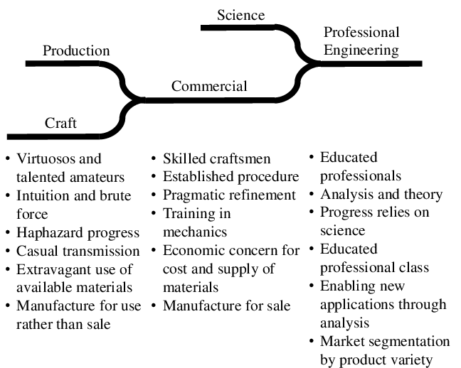
[Brockman2009] lists over 15 different engineering disciplines, like aerospace, chemical, civil, electrical, mechanical, and nuclear engineering. Before we judge whether software engineering deserves to be on that list, let’s look at software in more detail.
Software
Software is a program for a computer.
A program is a sequence of coded instructions that can be inserted into a computer.
We distinguish two types of software:
- System software: operating systems, device drivers, and utilities.
- Application software: productivity software, graphics software, databases, browsers, games, and the like.
System software is essential for the functioning of a general-purpose computer, managing hardware and providing a platform on which application software runs. System software provides value to the end user indirectly, through application software.
Most of what follows should be applicable to both categories. In case of conflict, however, we’ll focus on application software, because the majority of software falls into that bucket.
In summary, software consists of instructions for a computer that tell it what to compute. Let’s look at the science of computing next.
Computing
Automata theory is the study of abstract computing devices, named machines or automata [Hopcroft2007]. The theory formally defines different types of automata and derives mathematical proofs about them.
Finite automata
The simplest types of automata are finite automata. Formally, a Deterministic Finite Automaton (DFA) is a tuple , where
- is a finite set of states the automaton can be in.
- is a finite set of symbols, called the input alphabet of the automaton.
- is the transition function mapping states to successor states while consuming input.
- is the start state.
- is the set of accepting states.
We can visually present a DFA using a transition diagram. For instance, the DFA may look like this for a suitable :
stateDiagram-v2
  direction LR
  [*] --> p
  p --> p: 1
  p --> q: 0
  q --> q: 0
  q --> r: 1
  r --> r: 0,1
  r --> [*]
An alternative description of a DFA uses a table format. A transition table shows inputs as rows, the current states as columns, and next states in the intersection of the two. For example, the PDA above looks like this:
| p | q | r | |
|---|---|---|---|
| 0 | q | q | r |
| 1 | p | r | r |
Let be a word made up of symbols such that . If there are transitions in such that , , etc. and , then accepts . The set of all words that accepts is the language of , .
For instance, the language of the automaton above is the set of strings composed of s and s that contain the substring .
Languages accepted by DFAs are regular languages. Regular languages have many applications in software. For instance, they describe keywords and valid identifiers in programming languages or the structure of a URL. They’re also useful in searching documents and describing protocols.
A Nondeterministic Finite Automaton (NFA) is like a DFA, except returns a subset of rather than a single state. In other words, an NFA can be in more than one state at the same time. It’s possible to convert an NFA to a DFA, so the languages accepted by NFAs are also regular languages.
An -NFA is an NFA with the extra feature that it can transition on , the empty string. In other words, an -NFA can make transitions without consuming input. It’s possible to convert an -NFA to a DFA as well, so the languages accepted by -NFAs are also regular languages.
Regular expressions are an alternative way of describing regular languages. They use the symbols of along with the operators (union) and (zero or more times) and parentheses. For instance, the regular expression defines the same language as the PDA above. We can convert regular expressions to DFAs and vice versa.
Regular languages can describe parts of programs, but not entire programs. The memory of a DFA is too limited, since it consists of a finite number of states. Let’s look at more powerful automata that define more useful languages.
Pushdown automata
A Pushdown Automaton (PDA) is an -NFA with a stack on which it can store information. A PDA can access information on the stack only in a first-in-first-out way. The stack allows the PDA to remember things, which makes it more powerful than a DFA. For instance, no DFA can recognize palindromes, but a PDA can.
Formally, a PDA is a tuple . We’ve seen most of these symbols already in the definition of DFAs. The new ones are:
- is the alphabet of stack symbols, the information that can go on the stack.
- is the initial symbol on the stack when the PDA starts.
The transition function is slightly different. It takes the current state, an input symbol, and the symbol from the top of the stack as input. It outputs pairs consisting of a new state and a string of stack symbols that replace the top of the stack.
- This stack string can be , the empty string, in which case pops an element off the stack.
- It can also be the same as the top of the stack, in which case the stack remains the same.
- Or it can be a different string, even consisting of multiple symbols. In that case, the PDA pops the top symbol off the stack and pushes the output string onto the stack, one symbol at a time.
We can visualize PDAs using transition diagrams, just like DFAs. The edges show both the input symbol consumed and the old and new top of the stack. For instance, an edge labeled between nodes and means that contains the pair . Here, , where .
A PDA can accept a word in two ways:
- By final state, like for finite automatons.
- By empty stack, which is a new capability compared to finite automatons. In this definition, when the PDA pops the last symbol off its stack, the input it consumed up to then is a word that it accepts.
These two ways of accepting words and thus defining a language turn out to be the same. Suppose a PDA accepts by final state the language . We can construct a different PDA that accepts by empty stack precisely . The converse is also true.
We call the languages accepted by PDAs the context-free languages. Context-free languages, like regular languages, have important applications in software development. Before we dive into those, let’s look at an alternative way to specify the context-free languages: context-free grammars.
A Context-Free Grammar (CFG), or just grammar, is a tuple , where
- is a set of variables. Each variable represents a language, or set of strings. Variables are building block for the bigger language that the grammar defines.
- is a set of terminals. A terminal is a symbol in the language the grammar defines.
- is a set of productions. A production is of the form , where is the head and is the body. A body consists of zero or more variables and terminals.
- is the start symbol.
For instance, a grammar for the palindromes over and is:
Where is the following set of productions:
We can derive a word from a CFG . Start with its start symbol, and recursively replace variables using the productions until only terminal symbols remain. The set of words we can derive from a grammar is its language, .
A parse tree is a tree representation of a derivation in a CFG . The root of this tree is the start symbol of . For some production , there is a child under parent and these children are in order.
Here’s an example parse tree for that derives the palindrome :
graph TB
  A[P]
  B[0]
  C[P]
  D[0]
  E[1]
  F[P]
  G[1]
  H[0]
  A --- B
  A --- C
  A --- D
  C --- E
  C --- F
  C --- G
  F --- H
The leaves from left to right spell the derived word.
Languages we can derive from CFGs are precisely the context-free languages. For every CFG that defines a language , we can construct a PDA such that . The converse is also true.
Context-free languages can recognize programming languages. A parse tree of a CFG for a programming language describes a single program in that language. For instance, here’s a fictitional parse tree for the infamous program in C:
graph TB
  Program --- Function --- Declaration --- TypeSpecifier --- int
  Function --- CompoundStatement --- Statement --- ExpressionStatement --- CallExpression --- Identifier --- printf
  CallExpression --- StringLiteral

  StringLiteral[""Hello, world!""]
We now have the vocabulary to describe the structure of a program and of programming languages. However, PDAs aren’t powerful enough to describe the runtime behavior of all but the simplest programs. Let’s next look at automata that can.
Turing machines
A Turing Machine (TM) is a generalization of a PDA where an infinite tape replaces the stack. This tape is a linear sequence of cells, one of which, the head, the TM points to. Initially, the input is on the tape, one symbol per cell, and the head points to the first input symbol. Left and right of the input, all cells are blank.
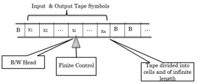
Formally, a TM is a tuple . We’ve seen most of these symbols already in the definition of previous automata. The new and changed ones are:
- is a set of tape symbols. These are analogous to the stack symbols of a PDA. Note that .
- is the blank symbol, where .
- The transition function takes a state and tape symbol as input. It produces a triple . Here is the next state. is the tape symbol written to the head. is the direction in which the head moves: = left and = right.
We can visualize TMs using transition diagrams, where edges are of the form . Here is the tape symbol at the head and is the replacement tape symbol. is the direction in which to move the head ( or ).
Several variations of TMs exist, such as those with multiple tapes or with the ability to keep the head in place. A non-deterministic variant exists as well. All these variations have the same power, in the sense that deterministic one-tape TMs can simulate them. Simpler models exists as well, like a PDA with two stacks, that can simulate a TM.
The languages TMs accept are the Recursively Enumerated (RE) languages. Like with the other types of languages, there are alternative models for expressing RE languages, for instance -calculus and general recursive functions. We call any model that accepts RE languages Turing-complete.
Real computers are Turing complete, if we assume the computer has access to an infinite number of disks of external storage. These disks simulate the TM’s infinite tape.
The Church-Turing thesis states that anything computable is computable by a TM. In other words, there can be no more powerful automata than TMs. Despite the lack of a formal proof, most people accept this thesis as true.
Programming a TM isn’t practical for solving real-world problems. The linear access model of a TM to its external storage, the tape, means the TM has to travel great distances. Real computers can access memory locations directly, which is much more efficient. Having said that, a TM is a useful abstraction to reason about computation.
Output
The transition function of an automaton gives the next state and, depending on the automaton, writes to external storage (stack or tape). We can change to also output something. A finite state machine that produces output is a transducer.
Conceptually, we can think of a transducer as a TM with two tapes: one for input and one for output. This implies that the output is a string of tape symbols from .
Output is often omitted in automata theory, which focuses on solving problems by accepting input. For real computer programs, however, output is crucial.
One may argue that the output of a TM is somewhere on its tape. This works for TMs and to some extent for PDAs, but not for DFAs. As we’ve seen, DFAs are useful in many situations in software development and some of those situations require output.
For instance, a tokenizer is a program that breaks a stream of text into individual tokens. These tokens may be part of a grammar, in which case we call the tokenizer a lexer or lexical analyzer. A program that analyzes text against a grammar and produces parse trees is a parser. The lexer must output the token it accepted, so that the parser can use it in its evaluations.
Model of software
Here’s a concept map of a software application based on automata theory:
graph
  Application --has--> State
  Application --allows--> Transition
  Transition --from/to --> State
  Transition --accepts--> Input
  Transition --produces--> Output
  Transition --reads from &\nwrites to --> ES[External storage]
This model is admittedly not super useful yet, but it’ll serve as the basis for later enhancements.
Now that we understand the basics of both software and engineering, let’s put these two together.
Software engineering
Software Engineering is the application of a systematic, disciplined, quantifiable approach to the development, operation, and maintenance of software; that is, the application of engineering to software.
The term software engineering was first used in the title of a NATO conference in 1968:
The phrase ‘software engineering’ was deliberately chosen as being provocative, in implying the need for software manufacture to be based on the types of theoretical foundations and practical disciplines, that are traditional in the established branches of engineering.
— [Naur1969]
Since then, people have worked towards this goal to make software development an engineering discipline.
SWEBOK
Some of that work has taken place at the Institute of Electrical and Electronics Engineers (IEEE). This professional association for electrical engineers and related disciplines discusses different knowledge areas in what they call societies.
The Computer Society (IEEE CS) “engages computer engineers, scientists, academia, and industry professionals from all areas of computing.” It also “sets the standard for the education and engagement that fuels continued global technological advancement.”
One of its publications is The Guide to the Software Engineering Body of Knowledge [SWEBOK].
The SWEBOK organizes material in knowledge areas (KAs):
- Software Requirements
- Software Architecture
- Software Design
- Software Construction
- Software Testing
- Software Engineering Operations
- Software Maintenance
- Software Configuration Management
- Software Engineering Management
- Software Engineering Process
- Software Engineering Models and Methods
- Software Quality
- Software Security
- Software Engineering Professional Practice
- Software Engineering Economics
- Computing Foundations
- Mathematical Foundations
- Engineering Foundations
Knowledge areas 16-18 provide the theoretical foundations. KA 10 describes the engineering process, while 1-9 cover the activities in that process. The other KAs deal with related topics.
Each knowledge area breaks down into topics and subtopics, summarizes the key concepts, and includes a reference list for detailed information.
IEEE CS stresses that SWEBOK is a guide to the body of knowledge for software engineering. The body of knowledge itself consists of the literature that SWEBOK references. Appendix C contains a list of 37 books that together cover all the KAs.
Is this actually engineering?
The SWEBOK uses the word “engineering” a lot, but is what it describes actually engineering? The year after SWEBOK V3 came out, Mary Shaw argued that what we’re doing in software development isn’t engineering [Shaw2015]. Alan Kay recently agreed [Kay2021]. This debate keeps flaring up from time to time [DeMarco2009], [Holub2023].
Some random data points further support this assessment:
- The Standish Group publishes a recurring CHAOS Report. The 2020 version states that 19% of IT projects are utter failures, and 50% fail in at least one way [Standish2020].
- The list of biggest data breaches ever shows that the top 10 all happened after publication of SWEBOK V3 [Statista2023].
These aren’t the results one would expect from engineering, so what’s going on? A complex question like that usually has more than one answer. Let’s look at some possibilities.
Management
Organizations achieve immensely different outcomes, even in level playing fields. Some organizations outperform their competitors in every important dimension, all at once.
[Kim2023] claims to understand why. The authors say all organizations are sociotechnical systems, where different types of work happen in different layers:
- The technical objects people work on, like source code.
- The tools and instrumentation through which people work on layer 1 objects, like compilers.
- The social circuitry: processes, procedures, norms, and routines, like software development processes.
They argue that performance in layer 3 dominates performance as a whole. In other words, winning organizations wire their social circuitry better. For instance, Agile methods outperform Waterfall [AgileVsWaterfall2023].
[Kim2023] offers the following tools to improve layer 3:
- Slowification to make it easier to solve problems.
- Simplification to make the problems themselves easier to solve.
- Amplification to make it obvious that there are problems that need solving.
Ignorance
Many software developers are unaware of the SWEBOK. I myself only found it when doing research for this book, and I’m an avid reader.
This problem goes beyond SWEBOK. For example, it’s been over 20 years since the [AgileManifesto], and there are still people doing waterfall because they don’t know any better.
Sometimes people do know better, but still stick to their old ways. This may be due to a lack of discipline, or it may result from poor management, as stated above. It’s also possible that they’re confused by too many options.
Too many options
The SWEBOK references more than one approach for most knowledge areas. Contrast this with Toyota. Its Toyota Production System (TPS) is an approach that combines all three tools for improving layer 3 [Kim2023].
Taiichi Ohno, TPS’s founder, says TPS is about reducing waste through just-in-time production and automation with a human touch [Ohno1988]. However, [Spear1999] shows that the real power of TPS stems from standardizing all work, while responding to problems by improving the standards. In other words, Toyota uses the scientific method, with the standards playing the role of scientific theory/hypotheses.
Is it possible to find one way to do software development that’s optimal in all situations? The answer is probably negative. [Spear1999] describes one Toyota plant with two divisions, where each division used a different approach. These approaches were the result of the divisions encountering different problems during their operation and solving them according to their unique situation.
And yet, there is an underlying way of working in those divisions. Companies following TPS have a common sense of what the ideal production system would be. Its output:
- Is defect-free (it has the features and performance the customer expects);
- Can be delivered one request at a time (a batch size of one);
- Can be supplied on demand in the version requested;
- Can be delivered immediately;
- Can be produced without wasting any materials, labor, energy, or other resources (such as costs associated with inventory); and
- Can be produced in a work environment that’s safe physically, emotionally, and professionally for every employee.
The Cynefin framework
Let’s look at this from the perspective of the Cynefin framework [Snowden2002] [Kurtz2003] [Snowden2007]. Here’s what its latest version looks like:
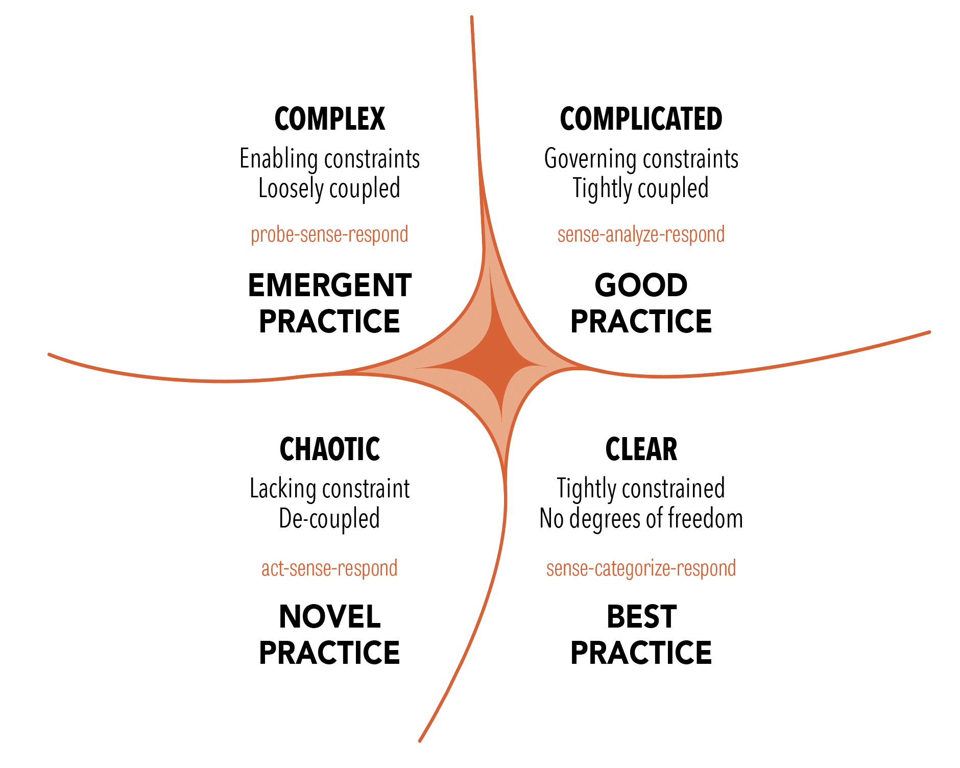
Software development isn’t in the Clear domain (formerly known as Simple and Obvious). Therefore, there are no best practices that everyone should follow no matter the situation. The question is whether software development falls in the Complicated or Complex domains.
Experts, such as engineers, rule the Complicated domain. The decision-making approach is to sense (get the facts), analyze, and respond. Here we use good, rather than best, practices, and can find multiple ways to success. This domain is the realm of the known unknowns, where at least one right answer exists.
In the Complex domain, there is no path to the one right answer. Here we’re in the realm of the unknown unknowns, where we can understand what happened only in retrospect. The best course of action is to probe (try something), sense (see patterns emerge), and respond. It must be safe to fail, or else people stop probing.
Consider a nuclear engineer designing a nuclear reactor. How often do they to have to adapt their design to the discovery of a new radioactive element or isotope? Never. If that did happen, they would throw away their design and start afresh.
Yet these types of requirement changes are what we see in software development all the time. This prompted the Agile movement to adopt a different way of working that embraces change [AgileManifesto].
That’s a sign that at least some parts of software development fall in the Complex domain. Signs aren’t proof, however. In fact, different aspects may be in different domains. This matters, because we should approach problems in the two domains differently.
Let’s look at the SWEBOK knowledge areas through that lens and see what we can learn.
The modern synthesis
If software engineering is to be the application of science to solve software development problems, then we need a science of software development. Some pieces of that are available to us, but we still need to synthesize a coherent picture.
Something similar happened in biology in the 20th century.
Evolution
Biology is the scientific study of life. While it has a broad scope, there is a unifying theory:
Nothing in biology makes sense except in the light of evolution.
— [Dobzhansky1973]
On a high level, evolution works as follows:
graph LR
  P[Parents &\noffspring] --Limited resources\nensure only the\nfittest survive--> Survivors
  Survivors --Survivors form\nthe new population--> Population
  Population --Parents produce\noffspring with\nsmall changes\nin traits--> Offspring
  Offspring --Offspring expand\nthe population--> P
Note how this process resembles the scientific method:
- The population is nature’s current theory on how to best adapt to their environment.
- Offspring inherit traits from their parents, but with small changes via mutation and, for species with sexual reproduction, crossover. In other words, each new generation contains several hypotheses on how to better adapt to the environment.
- Since resources are usually limited, only the fittest survive. Nature implicitly conducts experiments to falsify its hypotheses.
- The fittest organisms make up the new population, or current theory of how best to adapt to the environment.
The scientific theory of evolution rests on two pillars:
- Natural selection is the differential survival and reproduction of individuals due to differences in traits [Darwin1859] [Wallace1869].
- Heredity of traits is the passing on of traits from parents to their offspring with some changes [Mendel1866], [Fisher1930].
The two pillars of evolution were first brought together in the seminal book Evolution: The Modern Synthesis [Huxley1948].
The current book similarly aspires to bring together the various pillars of software engineering.
Book organization
The rest of this book attempts to answer the question of how to make software development a real engineering discipline.
We’ll first look into each of the SWEBOK knowledge areas to assemble the pieces. Then we’ll see if we can synthesize those into an actual engineering process.
Let’s get started.
Requirements
The SWEBOK gives [Wiegers2013] and [Sommerville2015] (chapters 3-5, 10, and 12) as the main reference material for the Software Requirements knowledge area. We first summarize that literature and then present a preliminary analysis.
ISO/IEC/IEEE 29148:2011(E) also covers requirements engineering [ISO29148].
Digest of requirements literature
In this section we review the generally accepted knowledge around requirements for software systems.
Definitions
Requirements are a specification of what should be implemented. They are descriptions of how the system should behave, or of a system property or attribute. They may be a constraint on the development of the system.
— [Sommerville1997]
[Wiegers2013] recognizes different kinds of requirements:
- Business requirements describe why the organization is developing a system; the benefits they hope to achieve in the form of a project vision, high-level business objectives, and success metrics.
- System requirements describe the requirements for a system that consists of multiple subsystems. An external interface requirement describes the connection between the system and other systems, hardware, or users.
- User requirements describe goals or tasks the users must be able to perform with the product to realize the business requirements.
- Functional requirements specify the behaviors the system must exhibit under specific conditions. They describe what the developers must implement to enable the user requirements.
- Quality attribute requirements or quality attributes describe the product’s characteristics in various dimensions that are important to stakeholders. Quality attribute requirements often apply to the system as a whole rather than individual features or services. They constrain the system, for instance by stating how fast it must respond.
These terms aren’t used consistently. For instance, [Sommerville2015] uses the term system requirement where [Wiegers2013] uses functional requirement. We’ll stick with the above definitions.
A stakeholder is a person, group, or organization that is actively involved in a project, is affected by its process or outcome, or can influence its process or outcome. Stakeholders can be internal or external to the project team and to the developing organization.
— [Wiegers2013]
Business rules, or domain requirements, are policies, guidelines, standards, or regulations that define or constrain some aspect of the business. They aren’t requirements themselves, but lead to requirements because they dictate properties that the system must have to conform to the rules.
A business process describes a series of activities that transform inputs to outputs to achieve a specific result. Business rules influence business processes by establishing vocabulary, imposing restrictions, and governing how to compute something.
A business rule falls into one of several categories:
- Facts are statements that are true about the business at a specified time. They describe associations between important business terms. Don’t go overboard with collecting facts; focus on the ones relevant to the scope of the product.
- A constraint restricts the actions that the system or (some of) its users may perform. It can be positive (something must happen or something must be true for something else to happen) or negative (something must not happen). Many constraints are about authorization, which you can capture using a roles and permissions matrix.
- An action enabler is a rule that triggers some activity if specific conditions are true.
These conditions may be complex combinations of simpler conditions.
A decision table captures action enablers in a concise way using
if-thenstatements. - An inference creates new facts from other facts.
If-thenstatements can capture inferences, where thethenpart specifies new knowledge rather than an action to take. - Computations transform existing data into new data using specific mathematical formulas or algorithms. Many such rules come from outside the organization, like tax withholding formulas. Capture computations in mathematical form or in decision tables.
Requirements engineering
Requirements engineering is the discipline that deals with requirements:
flowchart TB
  RE[Requirements\nengineering]
  RD[Requirements\ndevelopment]
  RM[Requirements\nmanagement]

  RE --> RD
  RE --> RM
  RD --> Elicitation
  RD --> Analysis
  RD --> Specification
  RD --> Validation
Requirements engineering is the realm of the business analyst (BA). This can be a job title or a role performed by people that also perform other roles. The analyst serves as the principal interpreter through which requirements flow between the customer community and the software development team [Wiegers2013].
For software used outside the organization that developed it, a product manager plays the role of business analyst. Both roles can also coexist, with the product manager focusing on the external market and user demands, and the BA converting those into functional requirements.
In Agile software development, the product owner plays the role of business analyst, although sometimes both roles are present.
Business analysts have their own body of knowledge [BABOK2015], including an extension for Agile software development [AgileBABOK2017].
Requirements development aims to collect good enough requirements to allow the team to start design and construction at an acceptable level of risk [Wiegers2013]. Requirements development is an iterative process of progressive refinement of detail.
Requirements engineering is a process and, like any process, we can improve it over time. Process improvement should be a continuous and evolutionary activity. Change is only accepted when people have an incentive to change. The biggest incentive is pain, so start by making problems visible by collecting metrics. These metrics serve as the baseline to compare improvements to. The Goal-Question-Metric (GQM) approach tells you which metrics to collect [Basili1982].
Perform root-cause analysis to determine improvement hypotheses. Pick one at a time and set clear goals for it. Treat improvement efforts as a mini-project, including proper planning, staffing, and change management. Make sure to revisit the goal to check whether the experiment worked using the metrics defined earlier. Keep in mind that change usually leads to an initial productivity drop while people figure out the new way of working [Satir1991]. Also, most metrics are lagging indicators, so it make take a while before improvements become visible.
Use a change budget to limit the amount of change to a level that people can absorb.
Elicitation
Excellent software is the result of well-executed design based on excellent requirements. Excellent requirements result from effective collaboration between developers and customers. This requires that all parties know what they need to be successful and understand and respect what their collaborators need. The business analyst forges this collaborative partnership.
A partnership requires that partners speak the same language, so learn the language of the business. Put together a glossary of terms, including synonyms, acronyms, and abbreviations.
A data dictionary stores more detail about terms in the glossary. It’s a shared repository that defines the meaning, composition, data type, length, format, and allowed values for data elements used in the application.
Stakeholders
In most cases, more than one category of user, or user class, exists. Some people call user classes stakeholder profiles or personas. User classes needn’t represent humans; they can also be external systems. Document user classes and their responsibilities, characteristics, numbers, and locations.
Direct users operate the product. Indirect users receive output from the product without touching it themselves.
The analyst works with the business sponsor to select representatives of each user class, known as product champions. Product champions gather requirements for all users in their class, so make sure they have the authority and trust required to do that. Ideally, product champions are actual users of the system.
If the product targets customers outside the organization developing the software, focus groups can take the place of product champions. A focus group is a representative group of users who convene to generate input and ideas for requirements.
The project’s decision makers must resolve conflicts between user classes. The primary stakeholders, also known as favored user classes, get priority.
Disfavored user classes are groups who aren’t supposed to use the product for legal, security, or safety reasons. Functional requirements for these user classes focus on making it hard for them to use the product. Examples are authentication to keep people from using the system at all, and authorization to prevent them from using specific features. In this context, some people talk about abuse cases that the system should prevent instead of use cases that make something possible.
Lack of adequate stakeholder involvement leads to an expectation gap, a gulf between what customers need and what developers deliver. To keep this gap to a minimum, arrange frequent contact points with product champions. Don’t limit this interaction to requirements, but involve users in as many activities as sensible.
Techniques
Elicitation is the process of identifying the needs and constraints of the various stakeholders. It focuses on how they do their work and how the system helps support that work. For any given project, you’ll probably need to use more than one of the following elicitation techniques:
- Hold interviews with individual stakeholders. Come prepared with questions and use active listening [Rogers1951]. When replacing an existing system, a good question is what annoys the user the most about it. It also helps to come with a draft model or prototype that the user can critique. Assign someone not actively participating in the discussion to take notes.
- Identify events. An event list identifies external events that trigger behavior in the system. Events originate from users, time, or external systems.
- Hold workshops with multiple stakeholders. These are especially useful for resolving disagreements, so hold them after using other techniques that surface those disagreements. Workshops may take on a life of their own, so refer to the business requirements to enforce scope and focus on the right level of abstraction for the session’s objectives. Smaller groups work faster than larger ones.
- Observe users do their work (ethnography). This helps understand the social and organizational context in which the work takes place. Limit sessions to two hours and focus on high-risk tasks. Use silent observations when you can’t interrupt users with questions.
- Distribute questionnaires. These are cheaper than alternatives when surveying large numbers of users. Their analysis can serve as input for other techniques that target smaller numbers of users.
- Analyze existing systems. Attempt to find the underlying need for offered features and assess whether the new system must address the same needs. Problem reports can give good ideas.
- Analyze existing documents. Examples are requirement specifications, business processes, user manuals, corporate and industry standards, and comparative reviews. Remember that documents may be out of date or incorrect.
- Analyze interfaces with external systems. This analysis gives technical requirements around data formats and data validation rules.
- Reuse requirements based on pre-existing business rules.
Different techniques work better for different user classes.
Elicitation is usually either usage-centric or product-centric. The usage-centric approach emphasizes understanding and exploring user goals to derive functionality. The product-centric approach focuses on defining features expected to lead to marketplace or business success.
A feature consists of one or more logically related system capabilities that provide value to a user and are described by a set of functional requirements.
— [Wiegers2013]
In usage-centric requirements elicitation, we capture user requirements in use cases. A use case describes a sequence of interactions between a system and an actor that results in value for the actor. An actor is a person or external system that interacts with the system.
A use case consists of one or more scenarios. The main success scenario describes the happy path of the interaction. Secondary scenarios, or alternative flows, describe variations in interaction, including those for error conditions. Each scenario has a description, trigger, preconditions, interaction steps, and postconditions. Exceptions describe anticipated error conditions and how the system should handle them.
Users may not be aware of all preconditions, so look to other sources as well. Business rules may drive some preconditions, like what role the user must have to perform the scenario. They may also define valid input values for or computations performed during the interaction steps.
Users know about those postconditions that relate to the value created for them, but those are usually not the only ones. Developers and testers often need postconditions that aren’t as visible to the user.
Activity or state diagrams can depict the interactions steps in a use case scenario.
The frequency of use gives a first estimation of concurrent usage and capacity requirements.
For products where the complexity lies outside user interactions, you may need other techniques besides use cases, like event analysis.
Stakeholders must establish acceptance criteria, predefined conditions that the product must meet to be acceptable. Without acceptance criteria, there is no way of knowing whether the product meets the requirement. Boundary values are especially interesting.
Use cases capture user requirements. They focus on the externally visible behavior of the system. To complete development, we need more information. The extra information takes the form of functional requirements that support the user requirements.
One example is about reporting. A use case may show that the system compiles a report for a user class, but not the details of the report. A report specification describes the purpose and contents of a report. A dashboard uses multiple textual and/or graphical representations of data that provide a consolidated view of a process. Dashboards and reports may show predictive as well as descriptive analytics, which require understanding the underlying models and statistical calculations.
Quality attribute requirements
Quality attributes define how well the systems works. Examples are how easy it’s to use, how fast it executes, and how often it fails. External quality attributes are important to users, while internal quality attributes are important to developers, operators, and support staff.
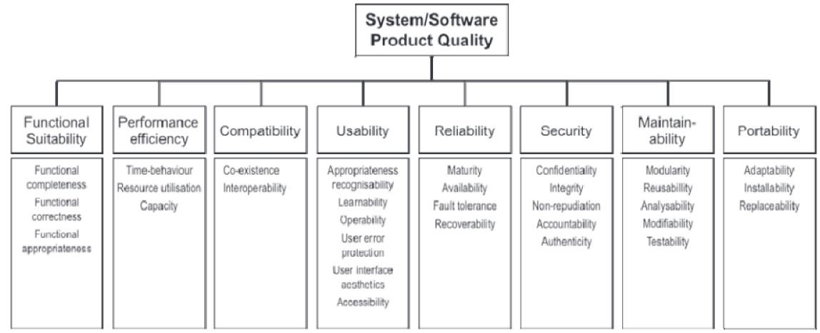
[ISO25010] defines eight quality characteristics, each of which consist of several quality attributes. Note that the first characteristic is functional suitability, which refers to functional requirements. ISO recommends you select a subset of quality attributes that are important for your system. For instance, hard real-time systems have stringent performance and efficiency requirements. Safety-critical systems place more emphasis on reliability.
Eliciting requirements for quality attributes is difficult. When given a choice, stakeholders always opt for the fastest, most reliable, most secure, etc. Ask them instead what defines unacceptable performance, reliability, security, etc.
The term dependability covers the related quality attributes of availability, reliability, safety, security, and resilience. Availability is the probability that the system is up and running and able to deliver useful services to users at any given time. Reliability is the probability that, over a given period of time, the system delivers correct services as expected by users. Safety is a judgement of the likelihood that the system doesn’t cause damage to people or the environment. Security is a judgement of the likelihood that the system can resist accidental or deliberate intrusions. Resilience is a judgement of how well the system can continue offering its critical services in the presence of disruptive events.
Quality attributes are emergent properties of the sociotechnical system, which contains hardware, software, and non-technical elements such as people, processes, and regulations. Sociotechnical systems are so complex that you can’t understand them as a whole. Rather, you have to view them as layers: equipment, operating system, networks, applications, business processes, organization, and society.
The society layer contains governments, which mandate that organizations follow certain standards that ensure products are safe and secure. Governments establish regulatory bodies with wide powers that enforce compliance with these rules.
A constraint places restrictions on the design or implementation choices available to developers. Constraints can come from stakeholders (like compliance officers), external systems that the product must interact with, or from other development activities, like transition and maintenance.
It’s easy to miss requirements:
- Assumed requirements are those that users expect without explicitly expressing them. Quality attribute requirements are often assumed.
- Implied requirements are those that are necessary because of another requirement.
- Different user classes have different requirements, so make sure to involve representatives of all user classes. For instance, the sponsor may not use the product directly, but may need KPIs that the product must collect measurements for.
- High-level requirements are often too vague. Decomposing them into more detail may bring to light other requirements, including implied ones.
- Another source of missed requirements stem from error conditions.
- A checklists of common functional areas may help to increase coverage.
Requirements may change as customers learn more and as the business evolves. See change management.
Try to keep design out of the requirements as much as possible. For instance, focus on user tasks rather than user interfaces. You can only go so far with that, however. For instance, sometimes you need to design (part of) the architecture to enable analysis of requirements. When dealing with systems of systems, you need to know whether the requirement is for the software or for a non-software component. You also need to know what the interface requirements are.
Reject the solutions that stakeholders often offer. Instead, describe the underlying needs that those solutions address. In other words, understand the job the customer is hiring the software to do [Christensen2016]. The Five Whys technique may help to go from a proposed solution to the underlying need [Ohno1988].
Reuse
It’s possible to reuse requirements, just like other software development artifacts. Reuse improves quality and increases productivity, but comes with its own risks, like pulling in unneeded requirements via links to related requirements.
Requirements reuse ranges from individual requirement statements to sets of requirements along with associated design, code, and tests. Reused requirements often need modification, like changing their attributes. You can copy requirements from another product or from a library of reusable requirements, or you can link them to a source. The latter makes it hard to change the reused requirements.
Glossaries and data dictionaries are good sources of reusable information. Common capabilities in products, like security features, are also good candidates for reuse. Software product lines, a set of software products in a family, share a lot of functionality and thus opportunities for reuse.
If the product replaces another system, then you’re always reusing requirements, even if implicitly. However, you shouldn’t carry over all requirements without evaluation. Look for usage data that allows you to remove features that are rarely used. Check features against the business objectives, since these may have changed. Also look for new requirements, including transition requirements. Remember that existing systems set expectations for quality attributes, like usability, performance, and throughput.
Requirement patterns offer a different form of reuse. They package considerable knowledge about a particular kind of requirement in a way that makes it convenient to define such a requirement. A pattern gives guidance about applicability, an explanation about the content in the requirement, and a template for a requirement definition. It also gives examples, links to other patterns, and offers considerations for development and testing.
While reuse saves you time, making requirements reusable costs extra time. Requirements management tools can make reuse of requirements easier and help with finding reuable requirements.
Analysis
Analysis involves reaching a richer and more precise understanding of each requirement and representing sets of requirements in multiple ways. A feature tree organizes features in logical groups and hierarchies.
Model the environment. A context diagram shows how the system fits in the ecosystem [Brown2016]. An ecosystem map is similar, but also shows external systems that the product doesn’t itself interact with.
Model the system. An analysis model is a diagram that depicts requirements visually, which sometimes makes it easier to find flaws. Analysis models blur the line between requirements and design, so be explicit about your intentions with a model.
The different analysis models each have their own strengths and weaknesses, so pick something based on your situation:
-
A Data Flow Diagram (DFD) shows the processes of a system, the data stores, any external systems, and the flows of data between them. You can nest DFDs by expanding a process into its own DFD. A level-0 DFD looks a lot like a context diagram.
-
A data model depicts the system’s data relationships. It provides a high-level view of the data, while the data dictionary gives the details. An Entity Relationship Diagram (ERD) is a common format for a data model. In an ERD, rectangles represent entities, the physical items, people, or aggregation of data. Entities are also known as records or data structures. Entities have attributes, which the data dictionary describes. Diamond shapes in the ERD represent relationships between entities. Numbers show the cardinality of the relationships.
Entities show up in data stores in a DFD. Their attributes appear in report specifications. A CRUD matrix correlates use cases with Create, Read, Update, and Delete actions on entities.
-
A swimlane diagram shows the steps of a business process or the operations of a software system. They consist of several lanes that represent different systems or actors executing steps. Swimlane diagrams can show what happens inside a process of a DFD. Standard notations are Business Process Model and Notation [BPMN2013] and Activity Diagrams [UML].
-
A State Transition Diagram (STD) shows state changes. We already saw this kind of model in the introduction. UML has a similar diagram known as a state machine diagram [UML]. Transition tables show the same information as STDs in matrix form. These models are especially relevant for real-time systems.
-
A dialog map shows navigation between screens of the system. It’s basically a user interface modeled as an STD. Dialog maps should show detailed screen layouts, but focus on the essence of the interactions.
-
A decision table lists the various values for all factors that influence the behavior of a system, along with the expected response. A decision tree shows the same information graphically.
-
An event-response table (aka event table, or event list) list all events that may occur in the system, along with the expected response. An event is a change or activity in the environment that requires a response from the system. A business event comes from a human user, a temporal event from the passing of time, and a signal event from hardware or an external system. The expected response depends on the system’s state. Event-response analysis is especially valuable for real-time systems.
-
Formal methods are mathematical approaches to software development where you define a formal model of the software. You may formally analyze this model to search for errors and inconsistencies, prove that a program is consistent with the model, or apply a series of correctness-preserving transformations to the model to generate a program. Large-scale automated theorem-proving software supports program proving. However, developing the proof obligations for theorem provers is a difficult and specialized task, so formal verification isn’t widely used.
The starting point for all formal methods is a mathematical model, which acts as the system specification. To create this model, translate the requirements, expressed in natural language, diagrams, and tables, into a mathematical language that has formally defined semantics. Constructing a formal specification forces a detailed analysis of the requirements and is an effective way of discovering requirements problems.
Different systems have differing needs for formality. Safety-critical, security-critical, and mission-critical elements of the system are good candidates for modeling using formal methods.
Prototypes
Prototypes are partial or preliminary implementations that make concepts and possibilities more tangible. Their main goal is to reduce risk, so only build them to address high-risk or high-impact issues. A prototype is an experiment to validate the hypothesis that requirements are sufficiently defined and that user interaction and architectural issues are sufficiently addressed. Seen from that lens, it makes sense to build several prototypes.
Prototypes focus either on user experience (mock-up) or technical soundness of a proposed approach (proof of concept).
Mock-ups, also known as horizontal prototypes, imply behavior without implementing it. They can be self-contained screens or a structure the user can navigate (dialog map). They often address the look and feel of the user interface. Mock-ups help stakeholders state requirements, because it’s easier to critique than to conceive, especially when it comes to completeness and errors.
A proof of concept, or vertical prototype, implements a slice of functionality from user interface through all the technical layers. Use it to test a proposed technical approach, or to optimize algorithms. Where a mock-up focuses on usability, proof of concepts focus on more technical quality attributes.
You can build mock-ups and proof of concepts with different precision.
Paper and electronic sketches or diagrams are low-fidelity prototypes used to explore functionality and flow. High-fidelity prototypes allow definition of a precise look and feel. Low-fidelity prototypes are faster to develop and thus allow for faster iteration on ideas. High-fidelity prototypes risk endless discussions about details, so remind everyone that we’re just trying to get the requirements right, not designing yet.
A throwaway prototype lives only as long as required to reduce risk. You build it as fast as possible, without regards for sound engineering practices. Stakeholders may pressure the team to grow a throwaway prototype into the final product, but this is seldom a good idea. It would be expensive to get it up to quality standards. Low-fidelity prototypes are less susceptible to this pressure than high-fidelity ones. Address this potential pressure up front by setting specific expectations about the purpose of the prototype, or what experiment you’re running. If you build a high-fidelity throwaway prototype, add in time delays to prevent stakeholders getting the wrong impression about performance.
An evolutionary prototype, in contrast, is an increment on the path towards a final product. It must therefore meet all applicable quality standards. When planned well, the first couple of increments can reduce risk just like for throwaway prototypes, although they take a bit more time to develop.
You’ll learn more from observing users work with a prototype than from asking them about it. Don’t forget to include all relevant stakeholders when evaluating a prototype.
Prioritization
Customers set requirement priorities based on the contribution towards business objectives. Priorities are especially important for quality attribute requirements, since conflicts between quality attributes are a fact of life. You need to define which quality attributes are most important for the system, so that developers can make proper trade-offs. Priorities may be different for different parts of the system.
Make sure to cover all stakeholders when setting priorities. It’s easy to forget about support staff, for example. Achieving consensus among all stakeholders may be challenging. Define a set of criteria upfront for judging whether one requirement has higher priority than another. Examples of such criteria are business value, technical risk, cost, time to market, and contractual commitments. In case of conflicts, favored user classes get preference.
One tool for resolving conflicts is a matrix of requirements against themselves, where the cells show which is more important. However, this approach becomes unwieldy for larger requirement sets.
A better tool is to divide all requirements into high, medium, and low. Assess each requirement on the dimensions of importance and urgency. Then urgent/important simplifies to high, not urgent/important to medium, not important/not urgent to low. Don’t do urgent/not important at all or, if you must, assign them low priority.
Most stakeholders assign high-priority to 85% of all requirements. To prevent that, run the important/urgent method again on just the high features, using the labels highest/higher/high instead of high/medium/low. Map high and higher to medium in the original set of requirements and keep only highest as high.
Quality Function Deployment (QFD) is a more rigorous technique. It’s based on the benefit provided by a feature, the penalty paid if that feature is absent, its cost, and implementation risk. Construct a matrix with these factors as columns and the requirements as rows. Each cell gets a value between 1 and 9, inclusive, and each factor gets a weight. Calculate the total value as the weighted average of benefit and penalty. Calculate the percentage of total cost and total risk as well. Then priority = value / (cost % + risk %).
Using QFD takes a lot of effort, especially since you need to calibrate the weights. You may want to spend this effort only for high priority requirements, as obtained by other methods, or when stakeholders can’t reach consensus.
Other prioritization techniques exists, like MoSCoW, or giving participants $100 to “buy” requirements. These often have considerable drawbacks, such as being open to gaming.
The priority of a requirement should be one if its attributes in the SRS.
A high-priority requirement may depend on a lower-priority requirement. In that case, the lower-priority requirement must come first despite its lower priority. Quality attribute requirements that affect the architecture should receive high priority, because rearchitecting is expensive.
Software has a cost, which developers estimate. Customers should respect those estimates. Some features may be expensive or even infeasible. Sometimes changing features can make them attainable or cheaper.
Priorities and cost estimates together make it possible to deliver maximum value at the lowest cost at the right time. Priorities may change over time.
Specification
Specification involves representing and storing the collected requirements knowledge in a persistent and well-organized fashion. We should record requirements in a shareable form, rather than using an oral tradition. They should also be version-controlled. Use templates for consistency.
Keep business rules separate from requirements, since their scope is wider. This allows reuse across products. Document the origin and expected frequency of change for each business rule. The business should own business rules, rather than the software development organization.
Specification documents
The Vision & Scope document contains the business requirements, scope, and business context. Other names for this document are project charter, business case document, or Market Requirements Document (MRD). Whatever the name, the business sponsor is the owner.
The vision provides a shared understanding of the desired outcome: what the project is about and should become. It applies to the product as a whole and should change only when the company’s business objectives do.
The scope defines what part of the vision the current project or iteration addresses. At a high level, it’s about what business objective to target. At a lower level, it’s about what features to include. Vision and scope together allow evaluating proposed requirements for project fit.
The vision and scope document also establishes priorities. Categorize the five dimensions (features, quality, schedule, cost, and staff) as either constraint, driver, or degree of freedom. Not all dimensions can be constraints or drivers; degrees of freedom allow responding to changes in requirements or project realities. For instance, many Agile methods treat schedule & quality as constraints, features & cost as drivers, and scope as a degree of freedom.
Collect functional and quality attribute requirements in a Software Requirements Specification (SRS). This practice enables downstream activities, like validation and change management. The SRS has different names in different contexts, like business requirements document, or functional specification.
The SRS refers to the Vision & Scope document. It also describes the user classes and any design and construction constraints, like which programming language to use or which standards to follow. Documenting assumptions may prevent serious issues. An assumption is a statement that the team believes to be true in the absence of proof.
Writing requirements down may be tedious, but the cost of doing so is small compared to acquiring that knowledge. Or relearning it in the future by new hires.
Learn just enough about requirements for prioritization, then flesh out more details when needed for design and construction. Label uncertain requirements as TBD and assign someone to resolve the issue.
Trace requirements back to their origin: business requirements, system requirement, or business rule. Record the stakeholders requesting each requirement.
Assign a unique ID to each requirement.
The best format for such IDs is a text-based hierarchical tagging scheme.
This practice gives rise to IDs like Product.Discount.Error.
Present requirements in different ways to stakeholders to reveal more insights. For instance, text vs diagram or use case vs acceptance test.
It’s often useful to group requirements by features (or even a feature tree) or by user class.
You may want to include a logical data model in the SRS, including how to collect, verify, process, protect, and destruct data. Descriptions of reports are also valuable.
Don’t forget to document quality attribute requirements, like for usability (including localization and internationalization), performance, and security. Also include requirements around migrations from existing systems.
To prevent recurring discussions, record rejected requirements and the reasons for their rejection.
The SRS should contain a glossary.
For a software product that’s part of a larger system, capture the system requirements in a Systems Requirements Specification (SyRS). Requirements in the SyRS may need decomposing into individual requirements for hardware, software, and humans.
Writing requirements
Excellent requirements are:
-
Correct. Requirements must accurately describe a capability that meets a stakeholder’s need. Formalize correctness using acceptance criteria.
-
Complete. Each requirement must contain all information necessary for validation and implementation. This includes what to do in case of errors.
-
Unambiguous. Natural language is prone to ambiguity, but is necessary since stakeholders can’t usually read formal specifications well enough to validate requirements.
Ambiguity comes in two forms. The first is when one person can see more than one way to interpret a requirement. The harder type is where different people each see only one interpretation each, but those differ from each other.
To reduce ambiguity, we often use semi-structured text to constrain the text a bit. Lists, tables, formulas, charts, and decision trees may be useful as well. Use terms consistently and as defined in the glossary. Synonyms are okay, as long as they’re in the glossary as well. Try to avoid adverbs, since they introduce subjectivity.
-
Necessary. Required functionality should provide stakeholders with business value in line with the business objectives for the product. This includes compliance with laws, regulations, and standards. Reject requirements that don’t contribute to the stated business objectives. Likewise, exclude business rules that don’t need implementing in software.
Requirements must come from a source that has the authority to provide requirements.
-
Feasible. It must be possible to implement the requirement in an economic fashion.
-
Prioritized. Again, economics come into play, this time to make sure we can work on the most important things first.
-
Verifiable. Write individually testable requirements, with a small number of related test cases each. The count of testable requirements is actually a metric for product size. Rephrase negative requirements into positives (where possible) so that they’re clearer and thus easier to verify.
Acceptance tests are programs that verify that the software meets its requirements. They map to individually testable requirements.
It’s best to use templates to specify requirements so that all these properties get addressed. For system requirements, [Wiegers2013] suggests the Easy Approach to Requirements Syntax (EARS, [Mavin2022]), which offers this template:
While <precondition(s)>
when <trigger>
the <system name>
shall <system response>.
The while and when parts are optional.
Preconditions define conditions that must be true for a requirement to become active.
The trigger defines a discrete event detected by the system that activates a requirement.
The system name must be explicit.
The system response defines what the system must do when the requirement becomes active.
For user requirements, [Wiegers2013] suggests a template from [Alexander2002] with this structure:
The [user class]
shall be able to [do something]
[to some object]
[qualifying conditions, response time, or quality statement].
Quality attribute requirements should be SMART: Specific, Measurable, Attainable, Relevant, and Time-sensitive. [Wiegers2013] gives this example for availability:
The system shall be at least 95 percent available on weekdays
between 6:00 AM and midnight Eastern Time,
and at least 99 percent available on weekdays
between 3:00 PM and 5:00 PM Eastern Time.
Such statements require precise definitions of the metrics used, such as available in the previous example.
Many measurements of quality attributes are lagging indicators. This means you can’t tell whether the system achieved its goals until after it’s been in operation for a while.
The SRS as a whole should have some desired properties as well:
- Complete. No requirement is missing.
- Consistent. Requirements don’t contradict each other.
- Modifiable. Requirement collections should have a browsable history, especially after baselining.
- Traceable. Link requirements both backward to their origin and forward to derived requirements and later-stage artifacts, such as code and tests.
Conceptually, each requirement is one record in a Requirements Development (RD) system. Requirements Development tools help eliciting requirements and judge whether they’re well-written. For instance, they can scan for vague and ambiguous words. RD tools offer different communication methods for stakeholders and some can convert text to diagrams.
Formal specification
It’s possible to define requirements more formally using specification languages like Planguage [Gilb2005]. However, stakeholders can’t understand a formal specification, so they can’t check that it accurately represents their requirements. Software engineers, who understand the formal specification, may not understand the application domain, so they can’t be sure the formal specification is accurate either. Therefore, the best way to specify requirements is still in natural language. Structured natural language, like used in the templates above, is often better than free-form text.
For safety-critical systems, the trade-off between understandability and rigor may be different and formal methods may be the right tool.
Formal methods rely on a formal model of the system that serves as the specification. These methods mathematically analyze the model and may transform it into more detailed representations, sometimes all the way to code, while preserving semantics.
Verifying a nontrivial software system takes a great deal of time. It requires mathematical expertise and specialized software tools, like theorem provers. It’s an expensive process and the costs increase disproportionately with system size.
An alternative approach is model checking. The models used by model-checking systems are finite state models, usually created from program code. The analyst identifies desirable system properties and writes them in a formal notation, usually based on temporal logic. The model checker explores all paths through the model and checks whether the desired properties hold for each of them. If a property isn’t guaranteed, the model checker outputs a counterexample.
Validation
Verification determines whether the product meets its requirements (doing the thing right). Validation assesses whether a product satisfies stakeholder needs and business objectives (doing the right thing). Since we’re discussing requirements here, we’ll use the term validation.
The goal of requirements validation is to ensure that requirements:
- Accurately describe system capabilities and that those meet stakeholders’ needs.
- Come from business requirements, system requirements, and business rules.
- Are complete, attainable, and verifiable.
- Are necessary, and enough to all meet business objectives.
- Are consistent with each other.
- Provide an adequate basis for design and construction.
Various studies suggest that errors introduced during requirements activities account for 40-50% of all defects found in a software product. The major consequence of requirements problems is rework. Rework often consumes 30-50% of total development cost, and requirements errors make up 70-85% of that. Requirements validation pays for itself by reducing such rework.
For stakeholders to validate requirements, they must understand them. This limits the forms the requirements can take.
Acceptance criteria
Stakeholders assess whether a product meets their requirements using acceptance criteria.
Ensure that all requirements have acceptance criteria and, if possible, acceptance tests. Examples of acceptance criteria that are unsuitable for capturing in acceptance tests:
- The number of open issues is under some maximum.
- Documentation is available.
- Users received training.
You can’t perform acceptance tests until you have running software, but just writing down tests often reveals errors, ambiguities, and omissions in requirements.
Automate acceptance tests as much as possible. Automated tests fall on a spectrum from behavioral to structural. Behavioral tests focus on testing the external behavior of the system without considering its implementation. Structural tests consider the internal structure, code, or logic of the system.
Developers may write structural tests before the code, in a practice known as Test-Driven Development (TDD) [Beck2002]. Developers mat perform behavioral tests, separate Quality Assurance (QA) staff, and/or end users in User Acceptance Testing (UAT). For bespoke software specifically developed for one specific customer, UAT is often part of the formal process where the customer accepts the software.
Some quality attribute requirements may require experts to validate them. For instance, many organizations hire penetration testers to validate security requirements. Other quality attribute requirements may be hard to validate because they state that some things should not happen, like safety and compliance requirements.
Inspections
Writing acceptance criteria isn’t going to catch all requirements issues. You also need to review them.
Requirements reviews can take an informal or more formal form. Informal reviews only catch the most glaring errors, inconsistencies, and gaps. It’s better to conduct a formal review, which produces an inspection report with details about the inspection and its results.
The best-known kind of formal review is the inspection [Fagan1976]. Participants in an inspection should cover the following perspectives:
- The author of the requirements.
- Stakeholders that requested the requirements.
- Developers and testers who are going to do work based on the requirements.
- Representatives of systems that interface with the requirements’ product.
The following roles partake in an inspection:
- The moderator plans and facilitates the inspection workshop. Part of planning is to provide participants with checklists that guide participants in what to look for, focusing on high-occurrence, high-cost errors. The moderator may assign specific kinds of errors to inspectors.
- The author is there to watch and learn and is otherwise passive.
- The reader goes through the requirements, paraphrasing each. This may surface different interpretations.
- The inspectors point out any defects they see. Inspectors come to the meeting prepared, having reviewed the requirements before the workshop.
- The scribe documents the found defects.
The average cost of fixing a defect found during inspection is about half an hour [Kelly1990]. In contrast, it takes between five and 17 hours to fix defects found during testing. Since it takes only 1.1 hours to find a defect, on average, inspections make economic sense.
The number of defects found per unit goes down as the number of units inspected goes up in a single session. Inspection sessions shouldn’t last more than two hours. People shouldn’t take part in more than two sessions per day. People also shouldn’t review the same requirements more than three times.
Validation doesn’t end with inspection. The author reworks the requirements to fix the defects found. After that, a follow-up meeting assesses the fixes. The inspection process should have clear exit criteria that define when the requirements are ready for design and construction.
Requirements management
Everyone must agree on the requirements:
- The sponsor agrees that the requirements achieve the business objectives.
- Customers agree that the requirements address their needs.
- Developers agree that the requirements are possible and verifiable.
A requirements baseline is a set of reviewed and agreed upon requirements that serves as the basis for development of a product or increment. When possible, organize requirements into related sets and deliver those sets incrementally. Breaking delivery down like this helps in dealing with changes.
Changes in requirements are inevitable:
- Stakeholders don’t know precisely what they want at te beginning of the project.
- Stakeholders can sometimes articulate what they want precisely only after seeing something that doesn’t quite match their vision (“I know it when I see it”).
- Business needs may change during the course of the project.
- The legal and regulatory environment may change.
Requirements typically grow 1-3% per month. The analyst should place a baseline under change and version control to deal with these changes.
Requirements management includes all activities that maintain the integrity, accuracy, and currency of requirements agreements throughout the project. The business analyst sets up requirement storage mechanisms, defines attributes, coordinates status, and monitors change.
Requirements have attributes, like origin, creation date, priority, and status. Common statuses include proposed, drafted, approved, in progress, implemented, verified, and rejected. Tracking the distribution of statuses throughout the project shows the progress the team is making.
Requirements Management (RM) systems help manage changes to requirements, track status, and trace requirements to other artifacts. RM tools range from generic issue trackers and wikis to specialized products. Some RM systems are part of larger suites or connected to issue trackers. The specialized tools generate some attributes and let you enter others.
Version control uniquely identifies different versions of requirements and requirement sets. RM tools offer version control and more.
For effective change control, there needs to be a change control process for proposing, evaluating, and deciding on requirement changes. The process should include a “fast path” to ensure that low-risk, low-investment change requests don’t get bogged down in bureaucracy. Capture the change control process in a change control policy before changes arrive. The policy describes the lifecycle of a change request and the roles involved.
The Change Control Board (CCB) executes the policy by accepting or rejecting changes. They assess change requests (see impact analysis below), make decisions, and see to implementation and verification of approved changes.
Change requests share similarities with defect reports, and you can use the same tools to track them. You should capture change request attributes, like requester, type, date received, status, etc.
A requirements volatility chart tracks the rate at which change requests arrive after a baseline. It should trend towards zero as the project nears completion. A sustained high rate implies a schedule risk. The CCB then may need to renegotiate schedule, staff, budget, or quality to accommodate changes. Tracking the origin of change requests may also be illuminating.
Impact analysis is the process of assessing the consequences of a change. A traceability matrix helps with impact analysis. A requirements traceability matrix is a set of links between requirements and other artifacts, such as design and code elements. It also links functional requirements to higher-level user requirements, business requirements, business rules, and system requirements. For products in some fields, like aviation, regulations dictate that you can trace requirements forward to design and code.
Quality attribute requirements often don’t trace forward to code. Some quality attribute requirements, like for security, trace forward to functional requirements, like authentication, that in turn do trace forward to code.
For all but the smallest projects, manually maintaining traceability is impractical. Commercial RM tools often offer traceability functionality. You still have to manually add most links, but then the tool can assist with changes.
Risk management
Requirements management relates to risk management. A risk is a condition that may cause something bad to happen. Risk management is the process of identifying, evaluating, and controlling risks before they harm your project:
flowchart TB
  RM[Risk\nmanagement]
  MP[Management\nplanning]

  RM --> Assessment
  RM --> Avoidance
  RM --> Control

  Assessment --> Identification
  Assessment --> Analysis
  Assessment --> Prioritization

  Control --> MP
  Control --> Resolution
  Control --> Monitoring
Typical requirements risks include inadequate stakeholder involvement, misunderstanding of requirements, incomplete requirements, infeasible requirements, and continually changing requirements.
Risk prioritization helps to focus on the risks with the highest exposure first. Risk exposure is a function of likelihood (probability of bad thing happening) and impact (magnitude of bad thing happening).
Risk resolution executes plans to deal with risks. Some risks have such low exposure, that you can just accept them. If not, you need to decide how to deal with the risk. If you’re lucky, you can transfer a risk to someone else. Most of the time, however, you’ll have to mitigate the risk, meaning you work to reduce its likelihood or impact.
You should document risks and track them over time to see if your plans are working. Use the condition-consequence format for documenting risks. One condition may result in several consequences. Most of the time it suffices to record likelihood and impact using a low/medium/high scale. These should change when a mitigation action completes, so reevaluate them then.
You should also collect ways of dealing with any risks that materialize.
Requirements concepts
flowchart LR
  Sponsor;
  DU[Direct\nuser]
  IU[Indirect\nuser]
  User;
  Compliance[Compliance\nofficer]
  Illity[Quality\nattribute]

  Sponsor --is a--> Stakeholder
  DU --is a--> User
  IU --is a--> User
  User --is a--> Stakeholder
  User --part of--> Class
  Class[User class]
  Class --represented\nby--> Champion
  Champion[Product\nchampion]
  Champion --is a--> User
  Class --represented\nby--> Focus
  Focus[Focus group]
  Focus --consists\nof--> User
  Compliance --is a--> Stakeholder
  Developer --is a--> Stakeholder
  Operator --is a--> Stakeholder
  Support --is a--> Stakeholder
  Support[Support\nagent]
  Stakeholder --provides--> Requirement
  Requirement --supports--> Illity
  Illity --measured by--> Metric
  Illity --defined in--> Standard
  Illity --defined in--> Law
  Law[Law or\nregulation]
  Requirement --has--> AC
  AC[Acceptance\ncriterion]
  AC --captured in--> AT
  AT[Acceptance\ntest]

  BR[Business\nrequirement]
  BR --is a--> Requirement
  Vision --captures--> BR
  Vision[Vision & scope\ndocument]
  UR[User\nrequirement]
  UR --is a--> Requirement
  UR --supports--> BR
  UC --captures--> UR
  UC[Use case]
  FR[Functional\nrequirement]
  FR --is a--> Requirement
  FR --supports--> UR
  SRS --captures--> FR
  SRS[Software\nrequirements\nspecification]

  System --is a--> Requirement
  System[System\nrequirement]
  SyRS --captures--> System
  SyRS[System\nRequirements\nspecification]

  Rule[Business\nrule]
  Rule --leads to --> BR
  Rule --leads to --> UR
  Rule --leads to --> FR

  Feature --bundles--> FR
Preliminary analysis
The books referenced by SWEBOK present generally accepted knowledge in the requirements engineering field. However, we feel that some issues remain:
- There isn’t always someone who can give us the requirements.
- Requirements elicitation takes a long time because the development team needs to learn the domain.
- Software has a certain shape that should affect how we express functional requirements.
- Guidance on specifying quality attribute requirements is thin.
- The Agile requirements process is misunderstood and weak.
Let’s explore these issues in more detail.
Unknowable requirements
The literature assumes that it’s clear what the system we’re about to build should do. This isn’t true until we achieve product/market fit, which means startups need a different process.
The Lean Startup movement assumes that until we achieve product/market fit, we can only find out what works by trying things out [Ries2011]. This would put requirements development in the Complex Cynefin domain, rather than in the Complicated realm of engineering.
The Build-Measure-Learn cycle in Lean Startup corresponds to the probe-sense-response approach suited for the Complex domain. Over time, this process moves the undertaking from Complex to Complicated. Once the company establishes product/market fit, its requirements process normalizes.
The issue of unknown requirements raises its head outside the startup scene as well. We can ask stakeholders what they need, but they’re always constrained by their current situation and thinking.
There may be requirements out there that, when realized, would significantly enhance the value the product delivers, but which nobody involved can conceive of. Remember the quote attributed to Henry Ford: “If I had asked people what they wanted, they would have said faster horses.”
In this book, we’re trying to establish an engineering discipline for software development, so we’ll focus on the Complicated domain. We therefore won’t pursue the issue of unknowable requirements any further, trusting that Lean Startup solves that problem.
Learning the domain
Once a company achieves product/market fit, it should have a clear sense of what jobs the customer is hiring the software for [Christensen2016]. These jobs always occur within a larger process in a certain domain.
Most engineering disciplines specialize around such domains. Engineers trained in that field speak the same language as the people requesting them to build a system. In contrast, software developers need to learn the language of the domain.
The requirements elicitation practices assume an analyst interviews various subject-matter experts (SMEs) and then writes down requirements. Different representations of the requirements help SMEs to validate them.
In this approach, it’s the business analyst who integrates the perspectives from various stakeholders. Once a sufficiently clear picture is emerging from those conversations, maybe a workshop brings all the stakeholders together to validate there is a shared understanding.
This approach has some issues.
Subject-matter experts, by definition, are experts. They’ve accumulated a lot of knowledge over a long period of time. It’s hard for them to think back to when they didn’t have all that knowledge. This makes it hard for them to know what to explain or not, and even what to mention at all. And since the business analyst is new to the domain, they don’t know what questions to ask. The result is an iterative process of discovery that takes a lot of time.
Worse, it’s uncommon for SMEs to be experts in the entire domain. More often, multiple SMEs each have a clear picture of one part of the process and nobody of the whole. This results in conflicting points of view, which need resolution before building software. However, it takes a while before the analyst knows enough to ask the hard questions and bring conflicts into the open.
Some modern techniques address these challenges. The most promising ones are domain story telling [Hofer2021] and event storming [Brandolini2013] [Webber2017].
Both approaches use workshops where the key stakeholders work together to build up a consistent picture of the entire process. They introduce just enough notation just in time for non-technical people to collaborate. They let the stakeholders and development team build up a domain model in hours or days rather than weeks or months.
During a workshop, the SMEs perform the integration of various perspectives rather than the analyst. By giving them a standard notation, non-experts can follow what they’re doing and force them to be precise. It allows them to ask the hard questions and bring conflicts out for resolution. Everybody’s learning compresses while the domain model emerges as a natural byproduct.
The domain model is a concept from Domain-Driven Design (DDD) [Evans2004].
The interaction between team members changes as all members crunch the model together. The constant refinement of the domain model forces the developers to learn the important principles of the business they are assisting, rather than to produce functions mechanically. The domain experts often refine their own understanding by being forced to distill what they know to essentials, and they come to understand the conceptual rigor that software projects require.
— [Evans2004]
The domain model is a set of concepts shared by everyone on the project, with terms and relationships that reflect domain insight. These terms and relationships provide semantics for a language tailored to the domain while being precise enough for technical development.
This language is the ubiquitous language, because it’s used everywhere: requirements, tests, code, etc. Using the same language prevents many misunderstandings and bugs. The basic terms in the ubiquitous language are the domain objects: entities and value objects.
An entity is anything that has continuity and an identity, like a customer. When we need to bill the customer, we care whether we bill Alice Brooks or Charlie Davis. An entity may refer to or contain other entities.
A value object is a concept without an identity, like an email address. For value objects, we only care about their attributes. Two email addresses with the same local name and internet domain are always the same, while two customers named John Smith can be different. A value object may contain other value objects, like when an address contains a zip code. An entity may refer to value objects, like when an order line item contains a quantity.
An aggregate is a cluster of associated domain objects that we treat as a unit for data changes. For instance, we can create an order with line items, but we can’t create individual line items without an order. The root of an aggregate is an entity, like order in the example. The aggregate may contain other entities, like line items. Anything outside the aggregate may only refer to the root entity.
A repository is where an application stores aggregates and later retrieves them. Each aggregate type has its own repository.
The combination of structured workshops and DDD allows the development team to learn the domain faster and better than traditional techniques. The DDD concepts also map to code constructs in a natural way, eliminating translation issues.
Which of the two approaches should we take: domain story telling or event storming? We believe the answer is both.
Domain story telling is a collaborative modeling technique that highlights how people work together. While the domain experts tell their story in spoken language, the moderator records the story as a diagram:
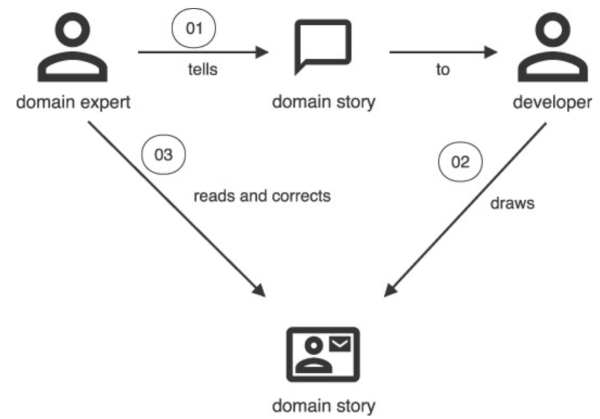
Domain story telling is more suited for requirements gathering and knowledge transfer from SME to the development team. Its main benefit is its simple pictographic language that’s easy to grasp for SMEs. This allows them to validate the requirements.
Event storming can work too, but in our experience, not as well. SMEs find it more natural to think about actors performing activities than about events that happened. This makes sense, given how humans evolved as social creatures.
However, event storming provides a great basis for high-level design and from there to tests and code. And it’s easy to elaborate a domain story into an event storm, as we’ll see later.
Requirements for software
Another potential issue with the generally accepted requirements engineering knowledge, is the advice to state requirements in relation to a user’s needs only. The point here is to keep design out of requirements, and that’s sound advice.
However, this approach also keeps out the fact that the requirements are for software rather than for manual procedures or for some other medium. Software has a particular shape and that should affect how we define requirements.
Most people suggest writing requirements as use cases consisting of scenarios and to do so in text form. Use cases and their scenarios describe processes in which the software plays a role. Rather than text, it makes sense to model these processes using to-be process models. This corresponds to the abstraction phase of the engineering design process where the engineer uses models to formalize the problem and get to solutions.
Whatever notation you decide to use to model processes, you’ll run into the problem that SMEs aren’t well-versed in it. This makes it hard for them to check the model. Therefore, we need a notation that we can automatically transform back to text that the SMEs can verify.
We also need a notation that allows us to decompose processes into smaller pieces. Finally, we need to tackle requirements in small batches, rather than all at once. We need to be able to decompose some parts of a process, while keeping others at a high level.
The international standard for modeling processes is Business Process Model and Notation (BPMN) [Dumas2018]. However, we’ll argue later that the model presented by event storming is actually easier to transform into a design.
Requirements should have acceptance criteria, predefined conditions that the product must meet to be acceptable in the operating environment. Without acceptance criteria, there is no way of knowing whether the product meets the requirement. The process model should guide us to the places where we need acceptance criteria, for instance where decisions get made.
At least some acceptance criteria take the form of acceptance tests. An acceptance test verifies whether the system meets a requirement. Some acceptance criteria can’t have acceptance tests, because they’re not about the system itself. For instance, stakeholders may require that the system comes with documentation.
Some acceptance tests run automatically as part of the product’s test suite; others are manual tests, like those in User Acceptance Testing (UAT).
[Adzic2009] argues that all acceptance tests, whether manual or automated, are best written using examples. Examples elaborate requirements and can become tests that verify the requirements. This template for specifying examples makes them easy to turn into tests:
Given <some initial state>
When <some input arrives>
Then <expect some new state and/or output>
This approach maps nicely to states and transitions of a Turing Machine or other automaton [Martin2008]. We therefore argue that at least all automated acceptance tests for functional requirements should take this form. For requirements around quality attributes other than functionality, this format may be too restrictive.
The Given/When/Then form looks a lot like the template used by EARS [Mavin2022].
The Given clause is a combination of the While and When clauses of EARS.
We prefer the Given/When/Then format, because it has more traction in the field and because it maps so nicely to
state machines.
Many requirements need more than one example to fully specify them. In such cases, it makes sense to condense the examples using a table. Tables also make it easier to spot missing combinations.
Given the order total is <total>
When the order is confirmed
Then the discount to subtract from it is <discount>

Examples:
| total   | discount |
| $99.99  | $0.00    |
| $100.00 | $1.00    |
| $250.00 | $5.00    |
Specifying quality attribute requirements
Quality attribute requirements are requirements that target a quality attribute other than functionality.
These requirements don’t deal so much with what happens, but more with how: how fast, how easy, how secure, etc.
That makes it less natural to express such requirements using the Given/When/Then format that focuses on the what.
For instance, for the quality attribute performance, we may use the metrics of throughput and latency. Throughput is the number of requests per second the system processes, while latency is the number of seconds it takes to handle requests.
We usually don’t care much about the latency of a single request being over 3 seconds. If this happens only once over the lifetime of a system, then that’s annoying but usually not a big deal. (Unless we’re talking about a safety-critical system, of course.)
The same holds for other quality attribute requirements. Consider usability, for instance. We may require that 90% of the users can find the right next action within 5 seconds of the system presenting them some information. We don’t care that one person one day was sleep-deprived and slow.
What we care about instead, is that some metric is below its threshold on average (50th percentile, or p50). Or in 95% of cases (p95), or some other statistical relationship. Often we want several such relationships to hold at the same time, like p50 3s and p95 5s.
The statistical nature of such requirements means we can’t test them with a single test, like we can for functional requirements. It also often means we must run the tests in production on real data to get meaningful results.
You may force acceptance tests for quality attribute requirements into the Given/When/Then format:
Given there are 100 concurrent users
When users search for some order
Then they receive search results within 3 seconds on average
However, this results in tests that are quite vague. What searches do the users perform? Are these searches finding the same orders? How many orders are there in the system? What’s the interval between searches?
We then risk such vagueness to spill over into the tests for functional requirements. That would be a shame.
A better format is the following:
- Objective: The quality attribute requirement under consideration. Define the quality attribute (performance, security, usability, etc).
- Scenario:
Describe conditions under which to test the quality attribute requirement.
This may involve setting up certain environmental conditions or specifying user interactions.
The scenario corresponds to the
Givenpart of theGiven/When/Thenformat. - Metrics: Outline the metrics to collect. Ideally, use one metric per requirement.
- Procedure:
Provide step-by-step instructions for conducting the test.
This may involve specific actions, measurements, or observations.
The procedure corresponds to the
Whenpart ofGiven/When/Then. Some people refer to this as the fitness function [Ford2017]. - Expected results:
Specify the thresholds or acceptable ranges for the metrics using percentiles.
The results correspond to the
Thenpart ofGiven/When/Then. - Constraints: Specify any limitations associated with the test, such as specific environments, user roles, or other contextual factors.
For example:
Objective:
    The search functionality is performant.
Scenario:
    System contains 100.000 records
Metrics:
    Latency of search
Procedure:
  100 users search concurrently on single keywords or short phrases.
  After an initial wait of 1-3s, each user searches, waits for 2-10s
  after seeing the search results, then searches again.
  The entire test lasts 5 minutes.
Expected results:
    p50 <= 3s and p95 <= 5s
Constraints:
    The test executes in the staging environment.
    Nothing else happens during the test.
Requirements engineering in Agile methods
Agile processes remain misunderstood. For instance, [Wiegers2013] describes user stories as comparable to use cases. They’re not.
In Agile processes, a user story is “a promise for a conversation.” Agile processes are lean, and user stories are a good example of their Just-In-Time (JIT) nature. We don’t want to waste time elaborating on requirements until we’re ready to implement them. A user story is a scheduling tool. We put user stories on the backlog until it’s time to work on them.
To schedule work, we need to understand its costs and benefits, so that we can prioritize it against other work. The product owner and development team discuss the work in just enough detail to get both. Once the team is ready to work on the user story in an iteration, it completes the requirements engineering work and implements the requirements.
The confusion around user stories comes at least in part from its name, which isn’t accurate. A user story is neither a story nor necessarily about a user. We can see this when we consider the canonical form of a user story:
As a <stakeholder>,
I want <some functionality>
In order to <get a benefit>.
The stakeholder may be a user, or it may be a non-user stakeholder, like a compliance officer, business sponsor, or developer. Here’s an example of the latter that shows that user stories are about work rather than requirements:
As a developer,
I want to upgrade Java to 21
In order to improve the code using new language features
A user story’s one sentence isn’t a story, as [Sommerville2015] thinks. This misunderstanding probably reflect the authors’ lack of experience with Agile methods. Part of that lack of experience stems from resistance to try out Agile methods. This resistance, in turn, partly comes from a real or perceived lack of rigor.
Some of that criticism is fair.
Agile methods like eXtreme Programming [Beck2000] have a strong oral culture around requirements. This works fine when staff turnover is low, but breaks down when people leave and others join frequently. The product owner is an especially critical role in that sense. New joiners have to rely on the shared memory of the existing team to relearn the requirements.
This process is both slow and error-prone in the face of fading memories. Having acceptance tests helps, but they can’t capture all acceptance criteria. And when they can, they still don’t explain the rationale behind them.
You also can’t link to a conversation people had in the past, so requirements tracing becomes impossible in an oral culture. That in turn makes it harder than necessary to perform an impact analysis of proposed changes.
It doesn’t have to be this way, though.
We don’t have to throw out the JIT baby with the oral requirements bath water.
We can evolve the requirements documentation just like we evolve the code.
Valuing working software over comprehensive documentation [AgileManifesto] doesn’t mean we can’t or shouldn’t write
documentation at all.
Remember, there is value in the items on the right (documentation) when written to serve a need rather than for its
own sake.
Architecture
The SWEBOK gives [Bass2021], [Budgen2020] (chapter 6), [Rozanski2012], [Taylor2009], and [Sommerville2015] (chapter 6) as the main reference material for this knowledge area. We first summarize that literature and then present a preliminary analysis.
ISO/IEC/IEEE 42010:2022 also covers software architecture [ISO42010].
Digest of architecture literature
Architecture concepts
Analysis
Decisions
Architectures are usually documented (if at all) as a series of views [Clements2010]. Those views are representations of the architecture, however, not the architecture itself. The architecture is the set of principal design decisions [Taylor2009].
A principal design decision is the description of the set of architectural additions, subtractions, and modifications to the software architecture, the rationale, and the design rules, design constraints, and additional requirements that (partially) realize one or more requirements on a given architecture.
— [JansenBosch2005]
Each principal design decision constrains the solution space of the system in its own way. As the number of decisions grows, the resulting viable part of the solution space shrinks. The selected architecture is a single point in this viable part of the solution space. Note that there may be other points that are viable as well; these are alternative architectures.
Let’s pretend for a moment that the multidimensional solution space has only two dimensions. Then we can visualize the relationship between architecture and principal design decisions:
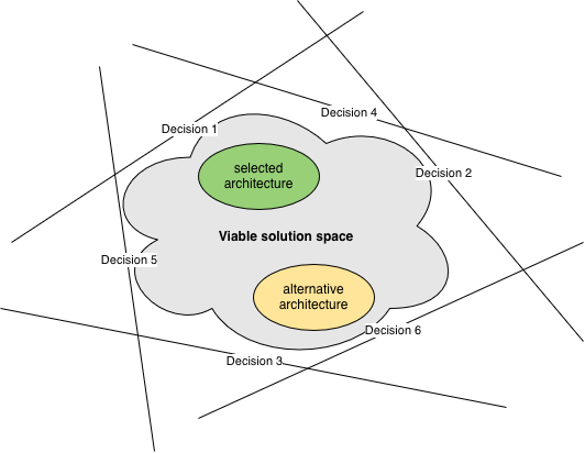
If architecture is the set of principal design decisions, then it makes sense to look more deeply into decision-making.
We already encountered the decision-making framework Cynefin [Snowden2007]. The unwritten assumption in the industry is that software architecture lies within the Complicated domain. The appropriate approach for that domain is Sense → Analyze → Respond, and that’s what architects do:
- Sense the functional requirements and quality attributes
- Analyze how they interact and compare them to other systems the architect has worked on or is otherwise familiar with
- Respond by making principal design decisions
Software architects seldom have formal training in decision-making and rarely use anything other than their experience (or fashion) to make decisions. Most are unaware of formal decision-making approaches, like Decision Intelligence [Pratt2023], and decision-making tools, like decision matrices [WikipediaDM].
Some decisions are impossible or very hard to reverse [Bezos2015]. We must then be very careful not to make the wrong choice, so using more formal approaches makes sense. Most decisions aren’t like that, however. It would be wasteful to spend a lot of time on them if we can change direction at low cost. Just because architectural decisions are principal design decisions, doesn’t automatically make them irreversible.
Architects rarely document their decisions. It then falls to others to reverse-engineer the decisions from the architectural views or from the code. The downside of this approach is that it’s impossible to retrieve the reasoning behind the decision. This leaves several questions unanswered, like
- What prompted the decision? What problem was the architect trying to solve?
- What was the situation at the time?
- What alternatives did the architect consider?
- What were the main decision drivers?
It makes sense to capture all that information in Architecture Decision Records (ADRs) [Nygard2011]. This is true even for decisions that are easy to reverse.
Up to this point, we’ve talked about decisions as if they’re a single thing. If we take the time aspect into account, however, we can make a distinction between “decisions we need to make” and “decisions that we made.” Where this distinction is important, we call the former issues and the latter outcomes.
Related decisions
Making one principal design decision is hard enough, but those decisions rarely come in isolation. Decisions have relationships with each other.
Some decisions constrain other decisions.
For instance, the choice of a programming language reduces the choices for what tools and frameworks to use.
The Go build command can’t compile Ruby code.
PyTest can’t test Rust code.
Using the Spring framework only makes sense with JVM languages like Java and Kotlin.
Some decisions replace earlier decisions. Things change, so what was once a prudent decision may now have serious negative consequences that require a different choice. For example, if maintainers of an open source library abandon it, you’ll no longer receive security fixes. Or if your company decides to standardize on AWS, your service running on GCP needs migrating.
Combining the above two relationships, it becomes clear that there is value in keeping options open [MaassenMatts2007]. For instance, tools like Bazel and Gradle can each compile several languages. Or organizing code in a Hexagonal Architecture [Cockburn2025] makes it easier to switch from Kafka to GCP Pub/Sub or AWS SNS & SQS.
Some decisions lead to further decisions. The definition of principal design decision mentions “additional requirements” that the architecture must meet. Follow-up design decisions must address these new requirements.
For example, suppose your application is running in a private datacenter, and you make the high-level decision to move it to AWS. Then there must be follow-up decisions about using EC2 vs ECS vs EKS, whether to use RDS or DynamoDB, etc. Or if you decide on a microservices architecture, then you also have to decide between storing code in a monorepo or in multiple repositories.
When looking at collections of decisions, it helps to organize them a bit.
We can group functionally related decisions into topics.
Another grouping is at which level we make a decision, for instance Executive, Conceptional, Technology, and
Vendor asset.
Adding those groupings gives us the following basic model:
flowchart LR
    Level --contains--> Topic
    Topic --contains--> Issue
    Issue --has--> Alternative
    Issue --decided in--> Outcome
    Outcome --selects--> Alternative
Now let’s look at expanding this model to define the above relationships between issues and alternatives more formally. [Zimmerman_et_al2009] define the following relations between issues:
- decomposesInto: We can use divide-and-conquer to split a decision into a set of smaller ones.
- refinedBy: We can make a decision at one level, which then requires another decision at a lower level.
- influences: This is a symmetric relationship that’s deliberately less well-defined.
They also define relations between alternatives:
- forces: If we select an alternative for one issue, that implies we must select a certain alternative for another issue.
- isIncompatibleWith: If we select an alternative for one issue, that implies we must not select certain alternatives for another issue.
- isCompatibleWith: Certain alternatives for one issue work well with certain alternatives for another issue.
The above are all structural relations. Zimmerman et al define a temporal relation as well:
- triggers: Choosing an alternative for one issue (which creates an outcome) makes another issue ready to resolve.
Given the right integrity constraints on these relations, we can capture a set of issues as a directed acyclic graph called a decision model [Zimmerman_et_al2009]. Here’s an example:
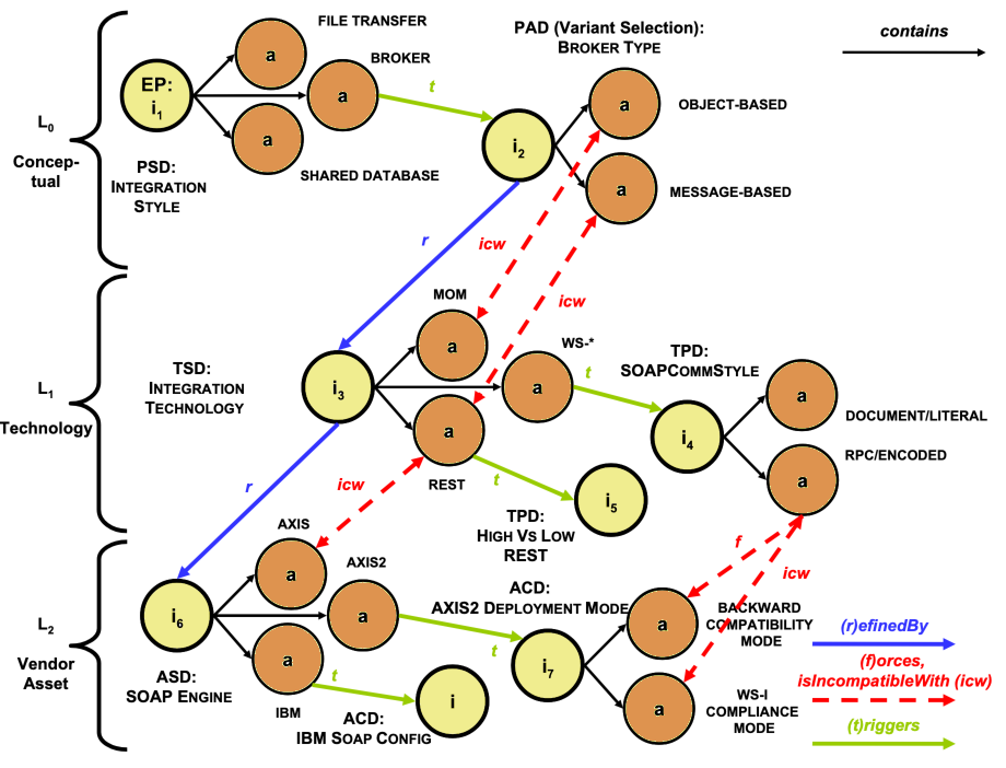
EP = Entry Point. PSD = Pattern Selection Decision. PAD = Pattern Adoption Decision. TSD = Technology Selection Decision. TPD = Technology Profiling Decision. ASD = Asset Selection Decision. ACD = Asset Configuration Decision.
A decision model has entry points, which are issues that are open for resolution. Once we make a decision for an entry point, other issues become open for resolution because of the triggers and other relations. In that way, the decision model guides the decision maker through a web of related decisions.
[Zimmerman_et_al2009] describe a Reusable Decision Model for SOA with 4 levels, 86 topic groups, and 389 issues. Architects can apply this decision model to any SOA project.
Architecture decisions
Now that we’ve looked at general decision-making, let’s turn back to architecture. If architecture is the set of principal design decisions, then it follows that architects must make decisions about important design alternatives.
[Kruchten2004] classify principal design decisions based on their impact:
- Existence decisions state that some element/artifact must exist in the systems’ design or implementation. Structural decisions relate to components, whereas behavioral decisions relate to their interactions.
- Non-existence decisions state that some element must not exist in the system’s design or implementation.
- Property decisions state an enduring, overarching trait or quality of the system. Property decisions can be design rules or guidelines (when expressed positively) or design constraints (when expressed negatively).
- Executive decisions don’t relate directly to the design elements or their qualities, but derive more from the business environment (financial), and affect the development process (methodological), the people (education and training), the organization, and technologies and tools.
Another grouping takes into account how unique decisions are, ie, how often they occur for different projects:
- Common decisions are those that architects need to make for (virtually) all software systems. For instance, every system benefits from a decision about its architectural style (layered, pipe-and-filter, event-based, etc) [Taylor2009]. Likewise, every system needs a programming language for implementation, along with build tool, testing framework, etc.
- Category-specific decisions are those that come up for certain categories of software systems. For example, every microservices architecture requires making a decision about how to deal with distributed transactions (choreography, orchestration) [Richardson2019]. Likewise, every event-based system needs decisions about what type each event is (notification, event-carried state transfer) [Fowler2017].
- Context-specific decisions are those that are unique for a given software system or small set of systems.
Architects must be well-versed in making common decisions. It may make sense for them to specialize in a certain category of architecture, to become proficient at category-specific decision-making as well. Finally, they must understand decision-making tools and techniques well enough to handle the inevitable context-specific decisions.
In theory, we should be able to create reusable decision models for common and category-specific decisions.
Design
The Software Design knowledge area deals with designing software.
The SWEBOK gives [Budgen2003], [Unknown bib ref: Sommerville2011], [Clements2010], and [Nielsen1993] as the main reference material for this knowledge area. We first summarize that literature and then present a preliminary analysis.
ISO/IEC 42010:2011 and IEEE Std 1016 also cover software design [ISO42010] [IEEE1016].
Digest of design literature
In this section we review the generally accepted knowledge around design of software systems.
The design process
Tools are artifacts we use to create other artifacts [Budgen2003]. Producing any form of artifact incorporates some form of design activity and software is no exception.
Most design problems have many possible solutions. No analytical method exists to arrive at the best solution, since it’s usually necessary to trade off different desirable characteristics. Designing is a so-called wicked problem [Rittel1973].
Designers have to work backwards from an intended outcome to activities that lead to that outcome:
- Postulate a solution
- Build a model of the solution
- Evaluate the model against the requirements
- Elaborate the model to produce a detailed specification of the solution
The input to the design process are the requirements, along with resource, organizational, and other constraints. Examples of the latter are a prescribed runtime environment or architectural style. The designer needs to acquire domain knowledge to communicate with users about requirements.
The output of the design process is an abstract model of the software. Typically, that consists of
- The static structure of the system
- The data used in the system
- The algorithms used to manipulate data
- The packaging of components that make up the system
- The interactions between the components
The design model consists of different views on the system addressing the above aspects. Each of those may require a different form of representation.
Design as a process leads to the design as the product. Design methods guide the designer through the process. Most design processes have two distinct phases:
- A closed box phase focusing on the problem, also known as architectural or logical design.
- An open box phase which focuses on the solution, also known as detailed or physical design. This phase maps problem units onto solution units, often via systematic elaboration.
We can speed up the design process by reusing parts of previous designs, for example using design patterns [Gamma1995].
Software design methods
The purpose of a design method is to provide the framework that enables the designer to develop the design in a systematic manner [Budgen2003]. Design methods consist of
- A representation part that provides descriptive forms of models of the problem and its solutions.
- A process part that describes how to transform the models. Each transformation takes a model as input and outputs another model, with the designer adding information. A transformation may keep the descriptive form of the model the same (elaboration) or change or reinterpret it (transformation of viewpoint). Each transformation is a design decision that the designer should record.
- Heuristics that provide guidance on how to execute the process part for specific classes of problems.
Most design methods lack a strong theoretical underpinning and are empirical in nature. They usually provide strategic guidance, rather than detailed instructions.
Documenting design using views
Usability engineering
Design concepts
flowchart LR
Preliminary analysis
Event storming
The event storming notation consists of the following items:
- A domain event is anything that happens that’s of interest to an SME.
- A command triggers an event.
- An aggregate accepts commands and emits events.
- A policy contains the decision on how to react to an event.
- A read model holds the information necessary to make a decision.
- A person is a human being responsible for a given decision.
- An external system is another system that interacts with the system under consideration.
- A hotspot is an unresolved item or group of items
In an event storming workshop, sticky notes of a particular color represent each of these concepts. Workshop participants place the stickies on a wall in timeline order to visualize the entire business process.
In the following, we’ll use custom symbols for these concepts, keeping the colors. This makes it easier to visualize processes.
A specific grammar governs event storming concepts [Brandolini2022], in the sense that certain things always come before or after others. It’s this grammar that allows people who aren’t domain experts to ask intelligent questions, like what emits this event?
The main part of the grammar is when a user of the system issues a command based on some information:
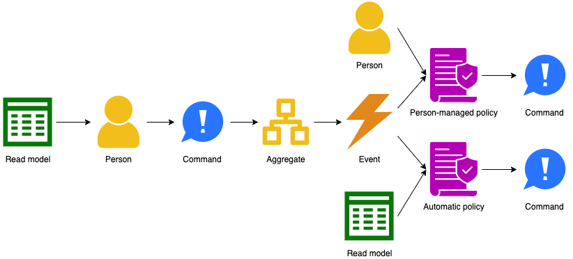
Some alternatives flows exist as well. An external system rather than a person may issue a command:

Events can also come from outside, either from an external system or from the passing of time:
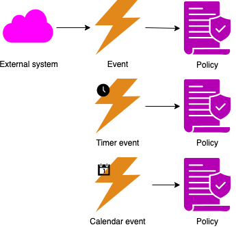
Events can update read models:

With the big picture defined, we can flesh out the domain model further.
DDD and event storming give us a new vocabulary to talk about what software does. We need to reconcile that with our vocabulary of what software is.
In event storming terms, aggregates make up an application’s state. An application transitions between states when an aggregate accepts a command. The output of an application is an emitted event.
Commands and events carry data. In DDD terms, that data takes the form of domain objects.
Putting all that together, we get the following model for a software application:
flowchart TB
  Policy --reacts to --> Event
  RM[Read model]
  RM --based on--> Repository
  Application --has--> Aggregate
  Aggregate --emits--> Event
  Policy --issues--> Command
  Aggregate --accepts--> Command
  Aggregate --defined by--> RE
  RE[Root entity]
  RE --is a--> Entity
  RE --stored in--> Repository
  Entity --is a--> DO
  DO[Domain object]
  VO --is a--> DO
  VO[Value object]
  DO --contains--> DO
  Entity --refers to --> VO
  Entity --bound\ninside--> Aggregate
  Command --contains--> DO
  Event --contains--> DO
  Application --has--> AP
  AP --is a--> Policy
  AP[Automatic\npolicy]
  AP --queries--> RM
  PMP --is a--> Policy
  PMP[Person-managed\npolicy]
  Person --executes--> PMP
  Person --initiates--> Command
  ES --issues--> Command
  ES[External\nsystem]
  ES --emits--> Event
Design method
- Put the requirements in Rigorous Event Storming Icon Notation (RESIN) and resolve hotspots. See the examples.
- If there are any humans issuing commands, or looking at read models, then design guidelines for the user experience.
- If there are any external systems issuing commands or consuming events, then design guidelines for the developer experience.
- For all events:
- Determine whether to use a notification event or event-carried state transfer [Fowler2017]. If the latter, determine what data the event carries.
- If an external system consumes the event, design the API.
- Determine whether the event requires an explicit queue with durability guarantees.
- For all commands:
- If an external system issues the command, design the API that allows the system to do that.
- If a human issues the command, design the user interaction that allows the user to do that. This includes designing the API from the frontend to the backend.
- Determine if the command requires synchronous processing. If not, prefer asynchronous processing.
- For asynchronous commands, determine whether the command requires an explicit queue with durability guarantees.
- For all read models:
- Design the data model using ERDs or similar notation.
- If the read model serves a human, design the user interaction that gives the user access to the data.
- If the read model updates from events, determine whether each event requires an explicit queue with durability guarantees.
- For all aggregates:
- Design the data model using ERDs or similar notation.
- Create a directed graph capturing dependencies:
- Add a node for every aggregate, read model, and automatic policy.
- Add an edge from an aggregate to a policy if the policy issues a command processed by the aggregate.
- Add an edge from a policy to a read model if the policy uses the read model to make a decision.
- Add an edge from a read model to an aggregate if the read model updates from an event emitted by the aggregate.
- Assign aggregates, automatic policies, and read models to subdomains based on the above dependency graph:
- For every aggregate:
- Create a domain containing the aggregate.
- For every read model:
- If all outgoing edges of the read model are to aggregates in the same domain, assign the read model to that domain.
- Otherwise, create a domain containing the read model.
- For every policy:
- If the policy has no outgoing edges, and all commands issued by the policy go to aggregates in a single domain, assign the policy to that domain.
- If a policy has outgoing edges, and they’re all to read models in the same domain, assign the policy to that domain.
- Otherwise, create a domain containing the policy.
- For every aggregate:
- Assign commands and events to the discovered subdomains as follows:
- Assign each command to the subdomain that contains the aggregate that accepts the command.
- Assign each event to the subdomain that contains the aggregate that emits the event.
- Assign each unassigned event to the subdomain that contains the policy that handles the event.
- Dependencies between modules follow from dependencies between the RESIN elements, in particular events and commands, since those are the modules’ APIs.
- If there are cycles between modules, then merge all the modules on each cycle into a single module.
Architecture
A module is a compiled and packaged subdomain, like a jar file. A component is an executable and deployable collection of modules, like a war file or executable fat jar.
— [Richardson2023]
Architecting consists of the following activities:
- Combine modules into components based on organizational structure and Quality Attribute Requirements [Richardson2023].
- Divide components into standard components to acquire (like databases and queues) and custom components to build.
- Select existing implementations for standard components.
- Decide how components interact.
- Select technologies to implement custom components and their interfaces.
flowchart TB
  R[Requirement]
  M[Module]
  C[Component]
  SC[Standard\ncomponent]
  CC[Custom\ncomponent]
  I[Interface]
  T[Technology]

  R --implemented by--> M
  M --deployed in--> C
  C --uses--> T
  I --uses--> T
  SC --is a--> C
  CC --is a--> C
  C --provides--> I
  C --requires--> I
Inputs to the architecting process:
- Requirements and the modules discovered from them
- Architectural styles and patterns
- Sanctioned technologies and vendors
- Teams and their skill levels
Outputs of the architecting process:
- Assignments of modules to components.
- Container diagram. Note that the C4 model uses different terminology: their container corresponds to our component and their component corresponds to our module.
- Architecture Decision Records (ADRs).
The starting point is an application consisting of a single system. Then analyze the quality attributes one by one to see if systems need splitting. Only make the architecture as complicated as it needs to be to meet the requirements.
Performance / scalability:
- Each aggregate and policy has implied queues for accepting commands and handling events. In theory, we can use queueing theory to analyze such systems. In practice, this approach runs into some issues, like unknown arrival and service time distributions. The theoretical models usually assume that work for server processes is independent and can therefore occur in parallel. In practice, this is seldom the case, and Amdahl’s law comes into play [Amdahl1967]. These problems mean that mathematical analysis is usually computationally intractable or at least impractical. It’s best to measure arrival and service times, store these as metrics, and then scale dynamically based on the collected metrics.
- Some commands require synchronous processing, because the caller needs a result right away. The latency for processing such commands is the latency of the entire process. For asynchronous commands, the latency is just the work for validating the input. Use asynchronous commands where possible, to give faster feedback.
- Split off command/event handlers that have significantly different scaling requirements into their own components, so they can scale independently.
Resilience:
- Make some queues explicit as components so that retries can handle issues during processing of commands/events. This requires that the handling code is idempotent.
- Split off command/event handlers that have a big risk of causing issues, like OOM, to reduce impact on other parts.
- Define what liveness means for each process. Consider using an orchestration tool (another component) to automatically restart processes that fail the liveness test.
- Consider load shedding when performance requirements aren’t met to preserve uptime. Detect this using the metrics defined in these requirements.
Security / compatibility:
- Commands arrive over a wire protocol. Apply input validation while mapping their data to domain objects.
- Apply output encoding when mapping domain objects to outputs.
Maintainability / portability:
- The domain model is more stable than technical parts, like what storage solution to use. Apply hexagonal architecture to isolate changes in those parts from the domain model.
Once done with quality attribute requirements, you should have identified all components. Perform make or buy decisions on all components. For each custom component, implement all functional requirements in the requirements group implemented by the component. Again, do one requirement at a time. Quality attribute requirements apply to all components.
Design
Design happens for each custom component:
- Collect all requirements in the requirements group that the custom component must implement.
- Implement requirements one at a time.
- For a given requirement, translate its acceptance tests into a list of detailed tests.
- Write code based on those tests using TDD.
flowchart BT
  R[Requirement]
  RG[Requirements\ngroup]
  CC[Custom\ncomponent]
  I[Interface]
  AT[Acceptance\ntest]
  UT[Unit test]
  C[Code]
  PL[Programming\nlanguage]
  T[Technology]

  AT --specifies--> R
  UT --implements\npart of--> AT
  UT --validates--> C
  C --implements--> CC
  C --implements--> I
  CC --implements--> RG
  R --is part of--> RG
  CC --provides--> I
  CC --requires--> I
  C --written in--> PL
  UT --written in--> PL
  PL --is a--> T
Canon TDD:
- Write a list of the test scenarios you want to cover.
- Turn one item of the list into an actual, concrete, runnable test.
- Change the code to make the test (& all previous tests) pass (adding items to the list as you discover them).
- Optionally refactor to improve the implementation design.
- If the test list isn’t empty, go back to #2.
Issues:
- How to order the initial list of tests? Select one which requires the code transformation with the highest priority.
- How to design the code-level API when writing a test? How to test quality attribute requirements?
- Are the transformations in the TPP complete?
- How to perform the vague ones, like
statement->statements? - How to deal with big jumps?
- Is there an order to code smells as well?
- When should we fix a smell and when should we wait a bit?
Construction
Digest
Concepts
Analysis
Materials
The implementation step of the engineering design process requires the engineer to select the right materials to realize the design. Materials have properties, grouped in categories, that affect their performance in the solution. These properties follow from the material’s physical make-up: its atoms, electrons, and molecular structure.
Software works with bits rather than atoms. Bits, and collections of them, have properties too.
Information
Bits can represent static information. From this perspective, various properties are interesting:
-
Storage
- Durability
- Format
- Language
- Quality
- Freshness
- Correctness
- Completenes
- Volume
- Size
- Compression
-
Privacy
- Classification (public, confidential, personal, protected)
- Permission (consent, legitimate use)
- Lineage
- Non-repudiation
Process
Bits can also represent a process that manipulates information. From this perspective, other properties are interesting:
- Transfer
- Style (synchronous, asynchronous, fire & forget)
- Control (push, pull)
- Protocol
- Throughput
- Latency
- Transformation
- Type (projection, selection, aggregation, conversion, mutation, deletion)
- Concurrency control
- Reliability
- Availability
- Fault tolerance
- Correctness
- Usability
Other
Whether the bits represent static information or a process that operates on such information, there are properties that both forms have in common. Cost is an obvious one, but another important category is security (encryption, authentication, authorization).
Testing
If we look at acceptance criteria through the lens of an event storming process model, we see some specializations of
the generic Given/When/Then format.
For aggregates:
Given <the aggregate has some data>
When <the aggregate accepts a command>
Then <the aggregate has different data and/or emits an event>
For policies:
Given <the policy's read model returns some information>
When <the policy reacts to an event>
Then <the policy issues a command>
For read models:
Given <the read model has some data>
When <the read model handles an event>
Then <the read model has different data>
Maintenance
Configuration management
Engineering management
Software engineering management is the collection of work activities involved with planning, estimating, measuring, controlling, coordinating, leading, and managing risk factors for a software project. Its purpose is to ensure delivery of software products and software engineering services effectively, efficiently, and to the stakeholders’ benefit [SWEBOK].
Digest
Concepts
Analysis
Measurements
A company’s main goal is to maximize profit by increasing revenue and reducing cost. A software delivery organization contributes to revenue by delivering product features. Its cost are mainly labor and infrastructure costs and as such outside the scope of this chapter.
The main metric: Service Level Expectation
Software delivery consists of building the right product in the right way. From an engineering management’s perspective, the latter refers to predictability and efficiency. We can measure both using a single metric: Service Level Expectation (SLE).
A Service Level Expectation is a probabilistic statement about how long it should take a work item to finish once started.
An SLE takes the form X% of work items finish in under Y time units once started.
— [Vacanti2015]
Let’s break this down:
- A work item is any direct or indirect discrete unit of customer value. This can be a user story, epic, feature, or entire project. Using a smaller granularity gives more data to calculate the SLE from and thus more robust results.
- You need to precisely define when a work item starts and finishes in your process.
- You can use any time unit you want, as long as you’re consistent with it. In practice, it’s often best to start with days.
- You should negotiate the value of X with the clients of the software delivery process, since it depends on their risk tolerance. However, any increase in X leads to an exponential increase in Y, so at some point adding more predictability makes the prediction useless. For instance, for X=100, Y is most likely in the order of years even for medium-sized work. In practice, it’s best to start with X=85.
- Given a value of X, you can calculate Y from measurements about each work item’s start and finish timestamps.
Here’s how to calculate the Service Level Expectation:
- For each work item, attach a timestamp when they start and when they finish.
- Calculate cycle time = finish timestamp - start timestamp + 1. The +1 is to make sure cycle time is never 0, since all work items require at least some time.
- For the reporting period, order the work items by cycle time.
- Y is the largest cycle time in the lowest X% of work items.
Benefits of using SLE:
-
It’s independent of the process used to deliver work. You just need to be able to define when work starts and finishes. For example, it works with both Scrum and Kanban, and even when you switch from one to the other.
-
It’s an absolute, objective metric, unlike, for instance, Story Points. This means you can aggregate at every desired level: from single team to whole organization. Just adjust the pool of work items.
-
Using SLE, you can say with confidence and at the desired accuracy when you expect work to get done. And this requires no estimation. All you need is to break work down into work items and some historical data about work items. About 10-30 finished work items is usually enough to get started.
-
The SLE calculation works even if your cycle times don’t follow a normal distribution, which is typical.
-
The SLE suggests how to improve software delivery: focus on reducing Y. Since Y only depends on start and finish timestamps, the options for reducing it are clear: focus on ways to finish work items faster. See below for concrete suggestions.
If you reduce Y enough, you may even increase X. That would result in a higher Y, which you can then work to reduce again, forming a continuous improvement cycle.
Common options for finishing work items faster are:
- Unblocking blocked work. Work that can’t make progress because of internal or external dependencies can continue to age well beyond the SLE. Getting unstuck is a powerful way to limit cycle time. You may even decide to cancel the work if you expect no progress soon.
- Lowering the number of concurrent work items the team is working on. Also known as limiting work in progress, or limiting WIP.
- Swarming, pairing, and mobbing happen when more than one person works on a work item at the same time. Swarming exploits parallelism in the work. Pairing [Williams2003] and mobbing [Pearl2018] [Meadows2022] remove hand-offs with associated wait times for activities like reviewing or testing.
- Automating more of the work by using better tools.
- Simplifying the work to remove unnecessary activities.
Additional metrics
SLE is the main metric for driving predictability and efficiency. Other metrics may help keep the process stable and drive improvements:
-
Capacity allocation: percentage of work items by type:
- functionality: building features
- quality: fixing bugs
- capability improvement: process improvements, process automation, code simplification, etc.
This metric enables a discussion about the right mix of investments.
-
Stability metrics:
- change failure rate: how often a rollback, hotfix, or incident occurs as percentage of all deployments
- escaped defect inflow: the number of customer-reported defects per reporting period
- open defect stock: total number of unresolved issues
These metrics ensure SLE improvements don’t degrade reliability and allow quality signals to inform quality-related capacity allocation.
Forecasting
SLE is a metric about the past. You can use it as a forecast for the completion of individual items if relevant things stay the same. An example of something that’s relevant is the composition of the team working on the items.
However, most of the time we’re interested in forecasting bigger chunks of work. Let’s follow Agile nomenclature and call such a collection of work items an epic.
We mustn’t multiply the SLE by the number of items in the epic to arrive at a forecast for the epic. A single item has much higher variability than a collection of items, so we’d be overestimating the duration. The correct way to forecast duration of a set of work items, is to use Monte Carlo simulation:
- Randomly pick a cycle time from a past work item.
- Repeat this
Ntimes, whereNis the number of work items in the epic. - Sum the
Ncycle times to get a prediction. - Repeat this process a lot, say 10,000 times.
- Compute the required percentile of the predictions to get the forecast.
Engineering process
We first summarize that literature and then present a preliminary analysis.
Engineering process
Redundancy and diversity are techniques for developing dependable systems. We can also use them to develop dependable processes. In a dependable process, activities use redundant and diverse techniques. For instance, verification & validation may use code reviews, static code analysis, automated tests and manual tests.
Evidence that the team followed a dependable process is often important in convincing regulators that the organization complies with laws and regulations. To be convincing, the process must be explicitly defined and repeatable. An explicitly defined process has a process model that drives software development. The organization must collect data to prove the team followed the process as defined in this process model. A repeatable process is one that doesn’t rely on individual interpretation and judgement.
Dependable process are auditable, diverse, documentable, robust, and standardized. A dependable software development process contains quality management and change management processes.
Analysis
The software development process
Software development is a multistep process that starts with stakeholder needs and ends with running software that meets those needs:
flowchart LR
  B[Business\nstrategy]
  KPI[Key performance indicators]
  N[Stakeholder\nneeds]
  R[Requirements]
  S[Subsystems]
  AT[Acceptance\ntests]
  UT[Unit\ntests]
  C[Code]
  P[Package]
  E[Running\nsoftware]
  M[Metrics]
  F[Fitness functions]

  B --Drives--> N
  B --Measured by--> KPI
  UT --TDD--> C
  C --CI--> P
  P --CD--> E
  E -- o11y --> M
  R --Architecting--> F

  N --Requirements\nelicitation--> R
  R --Architecting--> S
  R --Requirements\nspecification--> AT
  AT --detailed\nspecification--> UT
  S --detailed\ndesign--> UT

  M --Compare--> Success
  F --Compare--> Success
  KPI --Compare--> Success
Ideally, this process is:
-
Iterative – The system starts small and grows over time by adding or changing parts. Each part goes through the process one or more times. This follows Gall’s Law:
A complex system that works is invariably found to have evolved from a simple system that worked. [Gall1977]
Using domain stories is a good way to start describing the parts.
-
Incremental – Each stage of the process refines work from earlier stages and/or adds information. This acknowledges that software development is collaborative knowledge work.
Let’s look at knowledge and how knowledge workers collaborate in more detail and then apply that to software development.
Knowledge
Knowledge work is work that requires extensive knowledge to perform. Knowledge is often contrasted with information and data.
Data comprises facts, observations, or perceptions (which may or may not be correct). Data represent raw numbers or assertions and may therefore be devoid of context, meaning, or intent.
— [Becerra2024]
Information is a subset of data, only including those data that possess context, relevance, and purpose. Information typically involves the manipulation of raw data to obtain more meaningful indication of trends or patterns in the data.
— [Becerra2024]
Knowledge in an area are justified beliefs about relationships among concepts relevant to that particular area.
— [Becerra2024]
Knowledge helps produce information from data or more valuable information from less valuable information. In this way, knowledge facilitates action, like making a decision. Such decisions lead to events, which generate more data.
Knowledge can be generic or specific. The latter, also known as idiosyncratic knowledge, is more interesting for the current discussion. It can be technology-specific, context-specific, or both.
Technology-specific knowledge is deep knowledge about a specific area. It includes knowledge about tools and techniques that are useful to solve problems in that area. People often acquire this kind of knowledge as part of a formal training program and then augment it through experience in the field.
Context-specific knowledge refers to the knowledge of particular circumstances of time and place in which people perform work. One can’t acquire context-specific knowledge through formal training, but only via working in the context.
Software development relies on both context-specific and technology-specific knowledge.
For instance, consider the architectural decision about how to distribute code over deployable artifacts. Three basic options exist: an unstructured monolith (big ball of mud), a modulith, or a set of microservices. Technology-specific knowledge tells us that the big ball of mud approach has severe downsides for applications of non-trivial size. It can’t tell us whether a modulith or a microservices approach is the right choice, however. For that, we need context-specific knowledge about team sizes, skill levels of team members, etc.
Knowledge resides in several different locations: people, artifacts, and organizational entities. As the number of knowledge workers that collaborate to solve a problem grows, it becomes more important to capture knowledge in artifacts.
Software development in professional settings is highly collaborative. Many specialized people contribute their deep knowledge to specific parts of the process. The software development team therefore needs to capture their knowledge in artifacts, like requirements documents, design diagrams, source code, and tests.
Knowledge management tools for software development
Typically, knowledge workers have systems at their disposal to create, process, and enhance their own knowledge. The practice of knowledge management (KM) evolved to support knowledge workers with standard tools and processes. KM tools used in software development range from generic, like word processors, to specialized, like Integrated Development Environments (IDEs) or deployment tools.
More specialized tools deliver higher value by automating parts of the process. This is especially important since software development has high accidental complexity [Brooks1986]. The software development team has to consider many things that have nothing to do with the problem to solve, but by how it’s solved.
Since software is eating the world [Andreessen2011], it’s become imperative that we improve the effectiveness and efficiency of the software development process. We therefore need more specialized tools that automate more parts of the process and reduce accidental complexity as much as possible.
Such tools need a good understanding of what’s going on. In other words, we need to embed technology-specific knowledge in them. This requires capturing as much of the knowledge worker’s knowledge as possible in structured artifacts. Where generic tools like word processors can work with unstructured content, specialized tools need detailed structure that provides context.
Consider the case of renaming something.
A word processor offers the tool of Search & Replace, where the tool either replaces everything or the human has to
decide for each occurrence whether to replace it.
An IDE, however, offers the Rename tool that makes this decision automatically for the human, based on its
understanding of the context.
In that sense, the Rename tool reduces accidental complexity compared to the Search & Replace tool.
To support specialized tools, we should store artifacts in files that are both human and machine-readable. Making the file formats machine-readable may mean humans need dedicated editors to work with the files efficiently.
Artifacts from one stage should link to the artifacts from earlier stages that they refine or add information to. This provides traceability, which helps with impact analysis of proposed changes. Stage-specific tools verify the links between artifacts to ensure the system is complete and correct.
One thing we can learn from Unix, is that it’s better to have more fine-grained tools than fewer coarser-grained ones. Having more tools means they each support a smaller part of the process. This allows both the tools and the artifacts to be more focused. This, in turn, makes it easier to implement tools and easier to review artifacts. It also makes it easier to optimize tools for quality attributes like performance and cost.
Having many small, focused tools that each transforms a particular artifact type into another leads to an architectural style called pipes and filters [Taylor2009].
Tools for software engineering
The discussion has so far been about a process and supporting tools for software development. This leaves open whether software development is an engineering discipline or not. If we wanted to go further and insist on engineering discipline, what would change?
Since engineering is the application of scientific principles to solve practical problems, we’d need a science of software development. This science formalizes technology-specific knowledge about how best to develop software and organizes it in a coherent scientific theory.
And then we need to build tools based on that scientific theory:
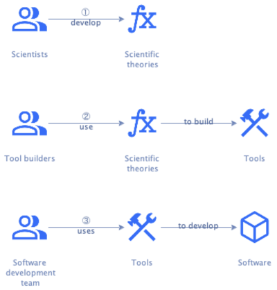
A set of such tools supporting the full software development lifecycle is a Software Engineering Workbench (SEW). A SEW should support and guide the software development process, helping teams adopt the right practices at the right time.
We can expect a science of software development to consist of several specific theories, each relevant to one or more stages. These theories define the rules for a given stage in the form of a coherent model and/or ontology. The science of software development needs to ensure these models map well onto each other, both forward and backward. Without such mappings, it would be impossible to support traceability and incremental development.
Software engineering as a team sport
Since professional software development is highly collaborative, a SEW must aid collaboration. The output of one member should flow effortlessly to the next, like a well-practiced sports team passing the ball around.
In our current reality, handoffs are usually not this smooth. A software development team resembles a team in a relay race more than, say, a rugby team (which is ironic when that team uses Scrum). The average software development team is more a collection of individuals who work in isolation and throw output over the wall than an actual team. Such handoffs imply queues with associated wait times, which can be significant.
A SEW should help the work flow faster through the team. It should collect flow metrics [Pereira2024] that identify and help the team improve the bottleneck [Goldratt1984]. It should also promote practices that improve flow, like software teaming [Pearl2018] [Meadows2022].
Most importantly, a SEW should make it easy to collaborate. It should make progress visible to all team members and make it clear where each can best contribute. In a way, this means that software engineering is a team sport where the players are both humans and tools. The tools ideally provide all technology-specific knowledge, while humans add context-specific knowledge.
A SEW thus consists of an orchestrator that maintains tasks for team members to complete, and tools that create or update artifacts. It supports team members by providing them tasks to perform, which also consist of creating and updating artifacts. Note that the creation of an artifact is usually the result of the transformation of one or more other artifacts by adding information. Updating an artifact is usually also a matter of adding information.
Engineering process concepts
The software engineering process is a specialized version of the knowledge management process:
flowchart LR
  P[Process]
  S[Stage]
  A[Artifact]
  T[Tool]
  O[Process orchestrator]
  H[Team member]

  P--consists of-->S
  S--deliverable\ncaptured in-->A
  T--supports-->A
  O--tracks-->A
  O--invokes-->T
  O--maintains-->Task
  H--performs-->Task
  Task--references-->A
The specialization lies in the tools and artifacts used. The chapters about the various stages of software development shed more light on the specifics. For instance, for the requirements stage, the artifact would be a domain story.
Engineering models and methods
Quality
Engineering professional practice
Engineering economics
Putting it all together
Software development is a process that results in running software, which is a process that automates part of a larger process. Given how central the notion of a process is to software development, it’s surprising to see how little attention it gets. Most architectural descriptions of software systems, for example, focus on its static structure.
Merriam-Webster defines a process as “a series of actions or operations conducing to an end.” A process is thus aimed at bringing about a change. On top of that, processes themselves change over time, as the business responds to changes in the internal and external environment.
Change is thus a fundamental aspect of software development, which is why the Agile movement urges us to embrace change [Beck2000]. However, the guidance on how to do that has been lacking. We’re told that a design should emerge from the code, and the architecture should evolve. We’re given some practices that help with that.
What’s missing is a worldview or philosophy [OReilly2024] and overarching approach of how those practices fit together. The following synthesis of the preceding material attempts to provide that.
Requirements
We should capture requirements with use cases and their scenarios [Wiegers2013]. Scenarios are actually just process descriptions.
The standard notation to capture processes is Business Process Model and Notation (BPMN) [BPMN2013]. However, this notation is complex: it has many symbols and nuances. These complexities are necessary to fulfill a major goal of BPMN: execute processes based on the model alone. As such, BPMN is more a tool for design and construction than for requirements gathering. A major problem using BPMN for capturing requirements is that stakeholders have a hard time reading BPMN diagrams and can therefore not validate the requirements.
Other notations exist for describing processes, like activity diagrams and sequence diagrams [UML]. These notations are simpler, but rather generic, containing not much more than actors, their actions, and some data flows. This makes it hard to use them to capture requirements and then derive a design from those requirements. It’s left to the designer to take a giant intellectual leap.
Event storming [Brandolini2013] can fill the gap between these two sets of notations. The concepts of events, commands, persons, external systems, etc. are easy to explain in a workshop format, especially when introduced gradually. The grammar that governs the concepts helps with uncovering requirements by directing participants to answer the right questions. The concepts are also powerful enough to turn requirements into design in a structured manner, as we’ll see.
The only downside of event storming is that it doesn’t come with a formal notation like BPMN or UML. It’s easy to replace the colored stickies with similarly colored icons, however, and connect them with arrows:
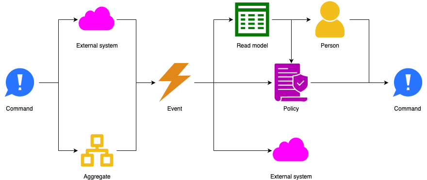
We call this Rigorous Event Storming Icon Notation (RESIN) and argue that RESIN is well-suited for capturing requirements and translating those into a design.
Note that we’re not suggesting to use RESIN in an event storming workshop. Stickies are more flexible and easier to manipulate. RESIN is for capturing event storms in a more formal way, as input to the rest of the software development process.
Requirements & logical design
You start off using RESIN in the same way as in the original event storming workshop:
- Brainstorm the significant things that happen in the process. Place orange event symbols on a timeline flowing from left to right.
- Ask what emits the events: external systems or the system under consideration. Place pink external system symbols for the former and red hotspot symbols for the latter.
- Next focus on the hotspots, since these show the incomplete parts of the process model. If it’s clear what specific part of the system emits a given event, replace the hotspot before it with a yellow aggregate symbol. Place a blue command symbol before the aggregate to make it emit the event.
- If it’s not clear what specific part of the system emits a given event, ask what stimulus leads to the system emitting the event. This is either a user instructing the system to perform an action, or a policy. Place either yellow person and blue command symbols before the hotspot symbol, or purple policy and blue command symbols to represent these possibilities.
- If a user issues a command, ask what information they need for that. If the system is to provide that information, place a green read model symbol before the person.
- Similarly, if a policy issues a command, it probably also needs a read model to feed it information.
- For each policy, ask what event triggers it. If an existing event does that, connect the event with the policy. Otherwise, place a new event symbol before the policy on the timeline.
- For each read model, ask what events feed information into it, if any. If an existing event does that, connect the event with the read model. Otherwise, place event symbols before the read model as appropriate.
- Repeat the above steps until no hotspots remain.
The result of the above process is a timeline that captures the process under consideration. It’s often hard to capture everything in a single timeline. That’s okay, you can use as many timelines as necessary to capture all scenarios of all use cases.
This process is a mix of requirements gathering and a bit of design, like determining the aggregates. That last part is actually nontrivial and deserves more attention.
Determining aggregates
Before we can get into the weeds of how to determine the aggregates, we need a better definition of what exactly an aggregate is. The “big blue book” defines aggregate as:
An Aggregate is a cluster of domain objects that can be treated as a single unit for the purposes of data changes. Each aggregate has a root and a boundary. The boundary defines what’s inside or outside the aggregate, and the root entity is the single entry point through which all interactions with the aggregate must occur.
— [Evans2004]
We can formalize this definition using precise mathematical language.
Let E be the set of all entities and D the set of all dependencies between them.
Then the domain model M=(E,D) is the directed graph of all entities and their interdependencies.
An aggregate A is a subgraph A ⊆ M with distinguished node r ∈ V(A) ∈ E, where:
- For every
e ∈ V(A) ∈ E, e ≠ r, there exists a directed path fromrtoewithinA. - For every edge
(e1,e2) ∈ E(A) ∈ D, ife1 ∈ V(A) ∈ Eande2 ∉ V(A), e2 ∈ E, thene1=r.
Every time you need to identify an aggregate in step 3 of the requirements/design process above:
- Determine the entity
e ∈ V(A) ∈ Ethat contains the required information for processing the commands and emitting the events. - If there is such an
e, determine which aggregateAhase ∈ V(A), and useA. - If there is no such
eyet, addetoE. - Determine whether
ecan exist on its own or needs another entitye2to exist. - If
ecan exist by itself, create a new aggregateA = ( {e}, {} ), and useA. - Otherwise, go to step 2 with
e = e2to find the aggregateAwheree2 ∈ V(A). AddetoV(A), add(e2, e)toE(A), and useA.
Acceptance criteria
To complete the requirements gathering phase, add acceptance criteria:
- For every aggregate, describe how it updates its data from the commands it accepts and how it emits events in response.
- For every policy, describe how it turns the events it handles into the commands it issues in response.
- For every read model, describe how it updates its data from the events it handles.
Of course, the above description is a simplification. In most cases, you’ll need several workshops to flesh out the details. You’re also going to have to redo some work as you learn more.
We think the above process works best when performed at different levels of abstraction:
- Do big picture event storming [Brandolini2013] to find use cases. The goal here is to identify hotspots.
- Hold more detailed event storming sessions to flesh out the details of a single use case or a small set of related use cases. The goal here is to resolve hotspots in one part of the system at a time.
By capturing requirements using event storming concepts, you’re well positioned to start designing the system.
Architecture & design
The process models captured in RESIN help split up the design work into manageable pieces. Those pieces are the event storming elements, which fall into the following categories:
- External: persons and external systems fall outside the scope of the system and therefore don’t need designing or architecting
- Active: aggregates, policies, and read models are the elements that make decisions (whether/how to update data, whether to emit events, whether to issue commands)
- Passive: events and commands just carry data from one place to the next
We need to design the active and passive elements. In the following, we’re going to look at architecture first and then at design, but you can also do it the other way around. You can even interleave the activities.
Architecture
A module is a compiled and packaged subdomain, like a jar file. A component is an executable and deployable collection of modules, like a war file or executable fat jar [Richardson2023].
The purpose of modules is to provide internally cohesive units with minimal dependencies on other modules. As stated above, a module is the technical equivalent of a subdomain. That means we can determine modules by determining subdomains.
Subdomains
We can leverage the power of the event storming grammar, which defines the valid patterns for event storm elements. Let’s look at the patterns between active elements:
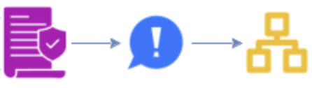
If a policy issues a command that an aggregate accepts, then it depends on the aggregate. It’s the aggregate that defines the contract for the command, because the command is part of its API. We call this contract coupling.

If an aggregate emits an event that a policy handles, then the policy also depends on the aggregate. The logic is similar: the event is part of the aggregate’s API, so it defines the contract.

This looks a lot like the previous situation, but it’s a little different. The read model depends on the agregate in this case too, but the coupling is actually a little stronger. Both aggregates and read models have associated data models (see below). If a read model updates its data based on an aggregate’s event, there is a good chance that these data models at least overlap. In fact, it’s likely that the read model’s data model derives from the aggregate’s. We call this data coupling, which is a bit stronger than contract coupling.

Here the policy uses data from a read model to make a decision on how to handle an event. The policy therefore depends on the read model. This coupling is much stronger than contract or data coupling, because the policy doesn’t just depend on the data from the read model. That data must be available at the moment the policy handles an event. We call this availability coupling.

Here one policy sends a command to an external system, and another policy handles the resulting event. Together, the policies implement an Anti-Corruption Layer (ACL) [Evans2004]. We therefore call this ACL coupling. The policies share a lot of knowledge about the external system, so this is a strong form of coupling: between data and availability coupling.
These five patterns give us a way to determine all dependencies between active event storm elements. We can then visualize the dependencies in a Design Structure Matrix.
A Design Structure Matrix (DSM) is a network modeling tool that represents the elements comprising a system and their interactions [Eppinger2012]. As such, a DSM highlights the system’s architecture.
Technically, a DSM is an NxN matrix, where the N rows and N columns each get the name of the system’s elements.
The diagonal of the matrix represents the elements.
Off-diagonal elements represent the dependencies between the elements.
In a binary DSM, the off-diagonal elements are either 0 (no dependency) or 1 (dependency).
Dependencies are usually marked with X, whereas empty cells represent no dependency.
In a numerical DSM, the off-diagonal elements are numbers representing the strength of the dependency.
Many other variations exist, for instance, using different colors for the cells.
We can use the dependency table for active elements to create a numerical DSM if we assign numbers to the coupling strengths:
- Availability: 10
- ACL: 8
- Data: 4
- Contract: 1
Note that there may be multiple dependencies between the same pair of elements. In such cases, we take the maximum coupling strength to get a single number for the DSM cell.
Having our dependencies in a DSM means we can re-use DSM clustering algorithms. The clusters found by those algorithms minimize the dependencies between the clusters and maximize the dependencies within the clusters. Since this is exactly what we want for our subdomains (and modules), we can find subdomains by looking at the DSM’s clusters.
We need one small refinement, however. It’s quite common to find two big clusters with a small one connecting the two. The small cluster contains a policy that handles an event from the first cluster and issues a command to the second. It depends on the preceding aggregate just as much as on the following (contract coupling), so the clustering algorithm puts it into its own cluster. Most of the time, we want to move the small cluster into one of the bigger two. This is straightforward if one of the two bigger clusters depends on the other. We then add the policy’s cluster to the one that depends on the other.
The subdomains we get from this procedure contain the active elements of the system. Let’s look at the passive elements next. Commands form the inbound API of an aggregate, so a command naturally belongs to the subdomain that contains the aggregate that accepts it.
The picture for events is a bit more complicated. There may be multiple aggregates emitting the same event, as well as multiple policies handling that event. However, we shouldn’t look at the individual emitters and handlers, but rather at their subdomains. For instance, there may be two aggregates that emit the same event, but both are in the same subdomain. This leaves us with the following combinations:
| Emitters’ subdomains \ Handlers’ subdomains | Single | Multiple |
|---|---|---|
| Single | Place event in emitting subdomain | Place event in emitting subdomain |
| Multiple | Place event in handling subdomain | Place event in a special “contracts” subdomain |
Components
Modules follow from the domains, which follow from the requirements. This is the easy part, since it depends on the technical system alone. Components, however, need developing and operating, which brings in the social part of the sociotechnical system. As a result, determining component boundaries isn’t as straightforward.
However, at a high level, we can play the same game as with subdomains / modules. We build a DSM where the elements are the modules and run a clustering algorithm on it. The problem is in finding the strengths of the dependencies between the modules.
TODO: Use Richardson’s dark matter/energy forces to define dependency strength between modules.
TODO: How does residuality theory factor in to create an architecture exhibiting criticality? Is this just the first step that defines the “naive architecture?”
Design
We need to design the active and passive elements of the system.
Events
Decide whether to use notification events or event-carried state transfer [Fowler2017]. Design the event payload. If an external system consumes the event, you’ll want to document the payload in a formal schema [AsyncAPI] [CloudEvents]. You also need to determine beforehand how to evolve the schema in the future, for instance using versions.
Clarify quality attribute requirements: is it acceptable to lose an event sometimes, or not? If not, you’ll need a message broker with appropriate durability guarantees. Likewise, is it acceptable for an event to arrive at the system multiple times? If so, the event handlers need to be idempotent. If not, the message broker needs to support exactly once delivery, which impacts latency.
Get a sense of how many events of a particular type the system must handle. If this sounds like a lot, you may want to do some modeling to get a feel of whether it’s feasible. Queueing theory models, like M/M/s [Kleinrock1974], may be useful to determine how many event handler instances you’ll need. You may need to do some prototyping to determine how long it’ll take to handle a single event before you can use such models.
Read models
Read models contain data, so we need to design their data models. Use ER-diagrams or similar notation for this purpose.
If the read model helps a user to issue a command, then a user interface must expose the read model. Design this interface and the interaction it’s part of.
If the read model feeds into a policy, then it needs an API. This API may be an informal one, where the policy accesses the read model’s data directly via a Repository or Domain Service. This approach is appropriate when the read model is part of the same domain as the policy, as discussed below.
Otherwise, design an internal API for accessing its data. Since this is an internal API, it may not need to same level as scrutiny and documentation as an external API.
If the read model updates its data from events, then consider the quality attribute requirements listed above.
Policies
Since policies handle events, consider the quality attribute requirements listed for event handlers.
Commands
Both aggregates and external systems can accept commands.
A command for an external system depends on that system’s API. This API can take many forms, but the important part for the current discussion is that it’s not something we need to design. The designers of the external system take care of that.
Commands accepted by aggregates come in two flavors. If a person issues the command, then they need a user interface to do so. Design this interface and the interaction it’s part of.
If, however, an external system or policy issues the command, then it needs an API to do so. Does the issuer need an immediate response (synchronous), can it wait for one (asynchronous), or does it not care about one (fire-and-forget)? For asynchronous and fire-and-forget scenarios, what delivery guarantees do we need?
Like with events, we need to design and document the schema for the payload of the API call. This can take various forms [OpenAPI] [AsyncAPI] [GraphQL]. We also need to design for throughput and latency requirements.
Aggregates
Like read models, aggregates contain data, so we need to design their data models.
Since aggregates accept commands, we need to consider quality attribute requirements around delivery, throughput, and latency. See events above for more information.
Testing
Construction
Examples
It often helps one’s understanding to see a theory in practice. Here we look at some examples of applying the theory of the previous chapter:
Example: supporting GDPR
In this example, a company owns several apps that consumers use. Since the company operates in the European Union, it must comply with the GDPR regulation. Among other things, this regulation grants EU citizens the right to have companies delete their data.
The company’s apps store data about their users. On top of that, the apps use shared services that also store data about those users.
Requirements
We start by discovering the requirements. For demonstration purposes, we’ll show this process in a simplified, structured form. The analyst asks a question, the stakeholder gives an answer, and the analyst shows the resulting model.
Q: What can I do for you?
A: I want a system to support GDPR:

Q: What interesting things happen in this system?
A: Users delete their data with it:
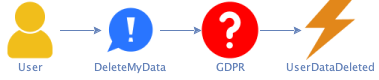
Q: How does the system know who the user is? Otherwise, it won’t know what data to delete.
A: The user either logs in to one of our apps and issues the command from there:
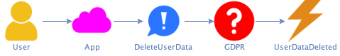
Or the user fills out an online form, and our customer support agents validate their identity against the apps’ user databases:
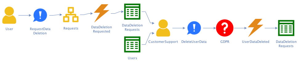
Q: What happens when the user’s request is invalid? For instance, when I use the form to request deletion of someone else’s data?
A: Customer support looks up the user via the provided email address. If there is no user with that address, we deny the request and the process ends. Otherwise, customer support contacts the user via email. If the user doesn’t respond in time, we deny the request. If the user responds they didn’t send the request, we also deny the request:
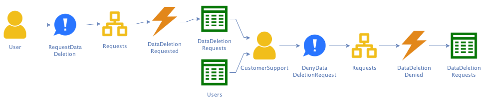
Q: How does the system know what users the apps have?
A: The app notifies the system of any changes in its users:
Q: How does the system delete the user’s data?
A: It has to tell all our services to delete the data. They’ll do the actual deletion and report back when they’re done.
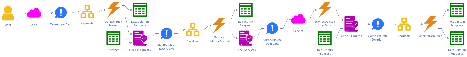
Q: What happens when a service doesn’t respond?
A: After some time, we’ll call them again.
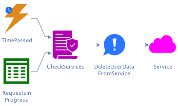
Q: What happens when all services have responded back?
A: Then the request is complete, and we inform the user.
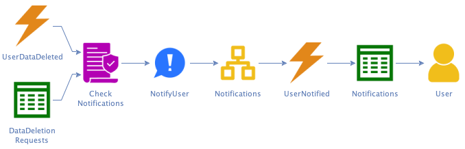
At this point, the process model is complete, since there are no more hotspots.
Note that the analyst did some initial design during the requirements elicitation process. Two situations makes this is possible:
- The model contains a sequence of command → hotspot → event where it’s clear what needs to happen in the hotspot and what information that requires. In that case, the analyst can replace the hotspot with an aggregate named after the required information.
- Similar considerations apply to a sequence of event → hotspot → command. Here, the analyst replaces the hotspot with a policy that takes input from a read model.
Just because the process model is complete, doesn’t mean we’re done with requirements gathering. We should define acceptance tests for automated policies, aggregates, and read models.
Design
The dependency graph for the above process looks like this:
graph
  dataDeletionRequestFormAggregate(DataDeletionRequestForm)
  servicesAggregate(Services)
  notificationsAggregate(Notifications)
  deletionsInProgressReadModel[[DeletionsInProgress]]
  dataDeletionCompletionReadModel[[DataDeletionCompletion]]
  checkUnresponsiveServiceAutomaticPolicy[/CheckUnresponsiveService/]
  checkRequestCompleteAutomaticPolicy[/CheckRequestComplete/]

  servicesAggregate --> checkUnresponsiveServiceAutomaticPolicy
  notificationsAggregate --> checkRequestCompleteAutomaticPolicy
  deletionsInProgressReadModel --> servicesAggregate
  dataDeletionCompletionReadModel --> notificationsAggregate
  checkUnresponsiveServiceAutomaticPolicy --> deletionsInProgressReadModel
  checkRequestCompleteAutomaticPolicy --> deletionsInProgressReadModel
- The graph has one cycle, so we create a module containing
Services,CheckUnresponsiveSerivces, andDeletionsInProgress. Let’s call this moduleServices, after its only aggregate. - We create two new modules for the unassigned aggregates
DataDeletionRequestFormandNotifications. - The read model
DataDeletionCompletiononly has one outgoing edge, so we assign it to theNotificationsmodule. - We assign the automatic policy
CheckRequestCompleteto the module that contains its read model,Services.
This gives us three loosely coupled modules:
graph
  dataDeletionRequestFormModule["<b>DataDeletionRequestForm</b>
- DataDeletionRequestForm
- DataDeletionRequested
- DeleteMyData"]
servicesModule["<b>Services</b>
- CheckRequestComplete
- CheckUnresponsiveService
- DataDeletedInService
- DataDeletionRequestedInService
- DataDeletionStarted
- DeleteData
- DeletionsInProgress
- RemindService
- Services
- TimePassed"]
notificationsModule["<b>Notifications</b>
- DataDeleted
- DataDeletionCompletion
- InformUser
- Notifications"]

servicesModule --> notificationsModule
Online classifieds
An online classifieds business is a two-sided marketplace, bringing together sellers and buyers.
Requirements
Users (buyers and sellers) need to register with the marketplace:

Sellers can then place classifieds ads on the marketplace:
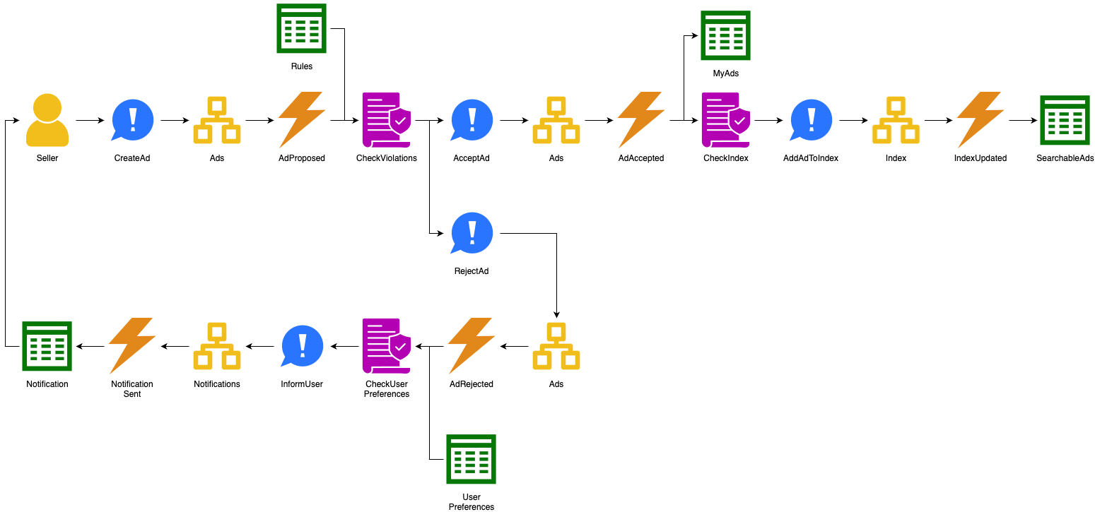
The marketplace maintains rules around what kind of ads sellers can place, and can reject ads that violate those rules. In this example, we assume such moderation happens automatically, but in practice this would be a combination of automated and manual processing.
The marketplace’s Trust & Safety (TnS) Manager defines the moderation rules:

The marketplace maintains a database of ads and also an index of searchable ads. The searchable ads contains a subset of all ads, optimized for searching by buyers. The seller can delete or change their ads:
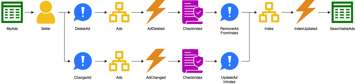
One of the ways the marketplace makes money is via paid features. For instance, ads age, which reduces their relevancy in the search index. Sellers can pay to bump their ads to increase this relevancy again:
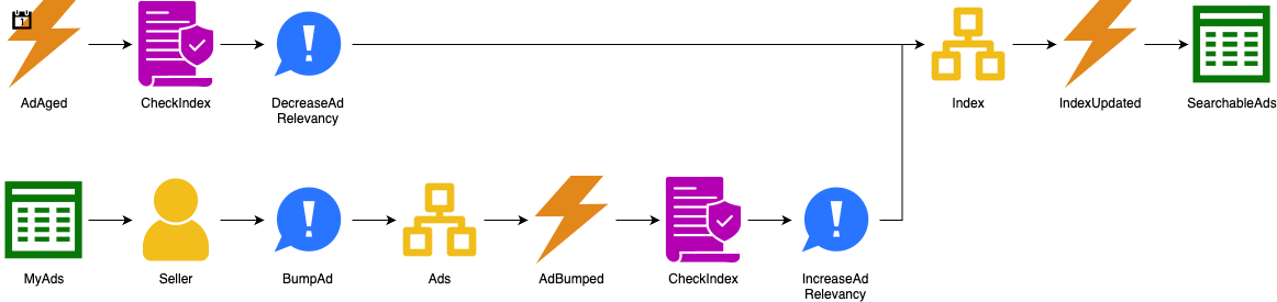
Buyers browse ads and make offers to sellers:
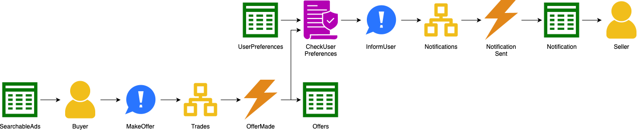
The seller can accept the offer:
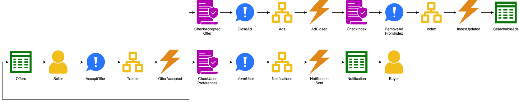
Or they can reject the offer:
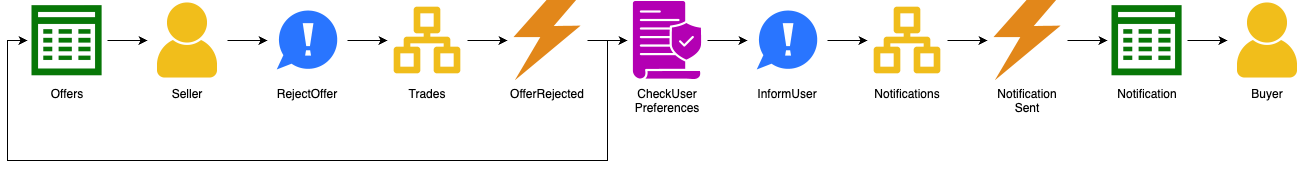
The above is a bare-bones classifieds experience. Competitive offerings include features not covered here, like messaging, payment, and shipping.
Design
The dependency graph for aggregates, automated policies, and read models looks like this:
graph
  usersAggregate(Users)
  userPreferencesReadModel[[UserPreferences]]
  adsAggregate(Ads)
  rulesReadModel[[Rules]]
  checkViolationsAutomaticPolicy[/CheckViolations/]
  myAdsReadModel[[MyAds]]
  checkIndexAutomaticPolicy[/CheckIndex/]
  indexAggregate(Index)
  searchableAdsReadModel[[SearchableAds]]
  checkUserPreferencesAutomaticPolicy[/CheckUserPreferences/]
  notificationsAggregate(Notifications)
  notificationReadModel[[Notification]]
  moderationAggregate(Moderation)
  tradesAggregate(Trades)
  offersReadModel[[Offers]]
  checkAcceptedOfferAutomaticPolicy[/CheckAcceptedOffer/]

  userPreferencesReadModel --> usersAggregate
  adsAggregate --> checkViolationsAutomaticPolicy
  adsAggregate --> checkAcceptedOfferAutomaticPolicy
  rulesReadModel --> moderationAggregate
  checkViolationsAutomaticPolicy --> rulesReadModel
  myAdsReadModel --> adsAggregate
  indexAggregate --> checkIndexAutomaticPolicy
  searchableAdsReadModel --> indexAggregate
  checkUserPreferencesAutomaticPolicy --> userPreferencesReadModel
  notificationsAggregate --> checkUserPreferencesAutomaticPolicy
  notificationReadModel --> notificationsAggregate
  offersReadModel --> tradesAggregate
The corresponding modules are:
graph
  usersModule["<b>Users</b>
- CheckUserPreferences
- SignUp
- UserAdded
- UserPreferences
- Users"]
adsModule["<b>Ads</b>
- AcceptAd
- AdAccepted
- AdBumped
- AdChanged
- AdClosed
- AdDeleted
- AdProposed
- AdRejected
- Ads
- BumpAd
- ChangeAd
- CheckAcceptedOffer
- CloseAd
- CreateAd
- DeleteAd
- MyAds
- RejectAd"]
indexModule["<b>Index</b>
- AddAdToIndex
- DecreaseAdRelevancy
- IncreaseAdRelevancy
- Index
- IndexUpdated
- RemoveAdFromIndex
- SearchableAds
- UpdateAdInIndex"]
notificationsModule["<b>Notifications</b>
- InformUser
- Notification
- NotificationSent
- Notifications"]
moderationModule["<b>Moderation</b>
- CheckViolations
- DefineRule
- Moderation
- RuleDefined
- Rules"]
tradesModule["<b>Trades</b>
- AcceptOffer
- MakeOffer
- OfferAccepted
- OfferMade
- OfferRejected
- Offers
- RejectOffer
- Trades"]

moderationModule --> adsModule
usersModule --> notificationsModule
usersModule --> adsModule
usersModule --> tradesModule
adsModule --> tradesModule